Print version of this Book (PDF file)
Extraction of DC/CV Parameters
Extraction of the complete BSIM3-, BSIM4-, or PSP-model parameters is done using two different modules. There is a module inside each Modeling Package for extraction of DC/CV parameters and a module for RF parameters.
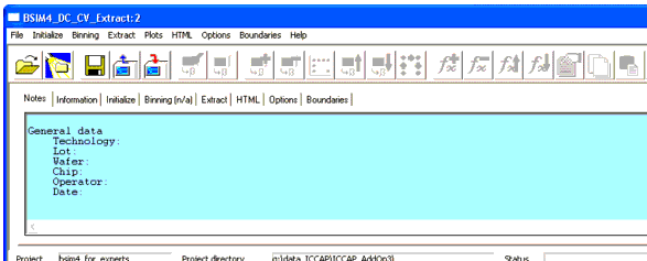
The following figure shows the GUI used for extraction purposes. You can see the folders for the tasks during the extraction process. Again, ordered from left to right are folders for Notes, for measurement Information, and to Initialize the extraction process. The next folders are used for Binning, to Extract parameters from measurement data, to create a report in HTML format for publishing the parameters extracted together with some graphics of simulations using the parameters extracted, and to set some Options and Boundaries for the parameters to be extracted.
Figure 30 GUI for the Parameter Extraction Process
The top row of the GUI window contains a menu to perform file operations like Open, Examples, Save Setup/Entries, Export and Import Extraction, and Batch Processing. The next menu items are used to Initialize extractions, to set Binning items and Extract options, to show Plots, to create HTML reports, to set Options and Boundaries, and to call the Help menu. The Help menu gives access to specific help for the different tasks during extraction of parameters. You'll find help for each folder of the BSIM Modeling Packages as well as a list of topics. The Info menu item provides some information about the BSIM Modeling Package like version, date, and its creators—AdMOS.
You can find most of the menu settings in the form of icons just below the menu. Some icons are only activated for specific tasks.
At the bottom of the extract window, you can find the project name and project directory used for the extraction.
Using the File > Examples menu, a form opens to let you copy an example project to a path and a location where you have write access. This step is necessary, since the IC-CAP example directories are usually write protected and you need write access to modify the example files.
If you would like to Open an existing project, select the project path and name in the Open Project dialog box. Using Export Extraction opens the Export Extractions form which enables you to choose path and name of the saved extraction settings file. It is not possible to create a non-existing path on Windows. Instead, you must create the desired folders, if non-existent, using the Windows Explorer.
Opening a project takes some time. You are able to reduce this time by saving the complete ~.mdl file. Reloading the ~.mdl file is faster than opening a project. However, since the ~.mdl file contains a large amount of data which is already stored somewhere in the system, you need to have extra storage capacity on your hard disc.
Note
You are able to Import Extractions by selecting the path and name of the saved extraction settings file inside the Import Extractions dialog box. This might be useful, for example, if you found a special extraction sequence that best fulfills the need of your parameter extraction process. You save those sequence by exporting the settings to a file and using this file as template for following extraction processes.
Importing extraction settings will overwrite the actual settings within the active extraction process!
Note
The Batch Processing menu option enables you to run extractions overnight, for example. It is possible to specify the path and name of several projects for extraction or for generation of HTML reports.
The tasks to be performed are ordered using different folders from the left to the right side of the BSIM3/4_extract window. They should be performed in this manner. Some of the folders have default values for your convenience. If you are satisfied with the defaults, those folders could be left as they are. However, you are not required to follow this order.
DC Notes
There is a folder provided to take some Notes on the project. It has the same look as the one used in the Measurement modules—see Figure 5, for example.
This folder is intended for notes on extraction. It will not overwrite your notes entered and saved during the measurement session. These are kept in the information folder.
Note
DC Information
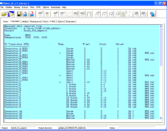
The next folder to the right gives you Information about the devices measured (see the following figure). You'll find the type of MOSFET, measurement temperatures, DUT names together with their geometries and categories as well as the notes entered during the measurement. If no measurement was performed on any of the DUTs, there will be a notice stating the incomplete measurement status at the end of the line for that DUT.
It is not possible to change the measurement information during the extraction session. This folder is for information on measurements only!
Note
Figure 31 Information Folder during Extraction
DC Initialize
The folder Initialize (Figure 32 for BSIM3 and Figure 33 for BSIM4/PSP) is intended to set initial conditions for parameter extraction. Since the initial conditions for BSIM3 and BSIM4/PSP models differ, the following section shows both Initialize folders, one after the other.
BSIM3
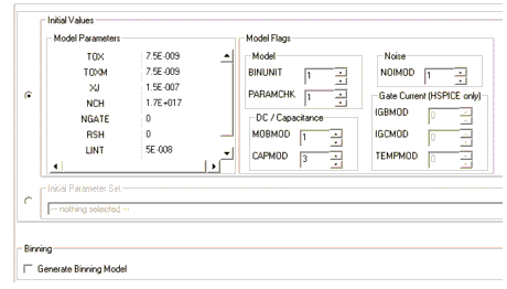
Figure 32 Initialize folder to set initial conditions for the extraction of BSIM3 parameters
The Initial Values section of the folder contains fields for Model Parameters and Model Flags. Into the field Model Parameters, enter process related parameters like oxide thickness (TOX) or doping concentrations (channel doping concentration NCH respective gate doping concentration NGATE), and so on. Entering values into the fields and selecting Save starts a routine to check the values entered. This routine will flag an error message and change the color of the field whose parameter is given an unrealistic value. The specific field will be marked with red color and remains red until the value is corrected.
The Model Flags section is used to set BSIM3 model flags. There are fields for global model flags like BINUNIT or PARAMCHK as well as fields for DC/Capacitance and Noise model flags. The model flags are set to a default value as has been described in the BSIM3 manual from UC Berkeley [1]. See Model Selection Flags for details or the above mentioned UCB manual [1].
If you are using HSPICE, a field is provided to set parameters for Gate current extraction.
A section called Initial Parameter Set is located below the Initial Values section. You can use a parameter set from any other extraction with IC-CAP, a circuit simulator (.cir) file, or a text (.model) file. Using the .cir or .model file requires you to specify an appropriate simulator. You enter the required information using the menu Initialize > Initial Parameter Set > Add. The form that opens enables you to enter the necessary information, browse to the file location, and select the simulator.
To change between using the Initial Values and Initial Parameter Sets, select the radio button to the left of each section. Select which initialization procedure you want to use.
If you would like to use the binning capability, check the Generate Binning Model button. With this button checked, the folder Binning is activated.
There is a field provided to enter PEL commands, which are executed at initialization of the extraction process.
Note that the sequence of initialization uses values of the model parameters first, before PEL commands are executed.
From the menu Initialize, chose Set Initial Values to Circuit Defaults if you would like to reset the parameters.
You can Add or Remove a Parameter from the list shown in the middle of the folder by selecting the Initialize menu. You will get a list with parameters to select from. This might be helpful if you would like to extract some specific parameters at initialization.
BSIM4/PSP
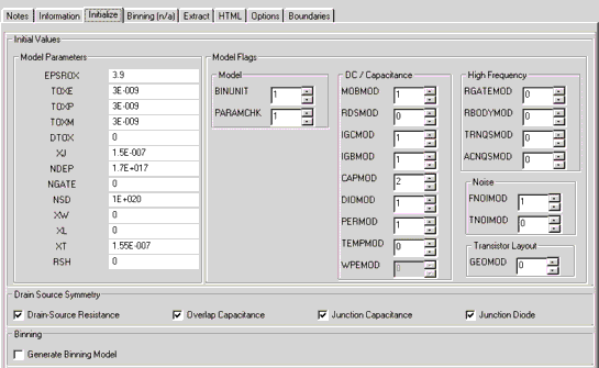
Figure 33 Initialize Folder for the BSIM4 Modeling Package
Figure 34 Initialization of PSP model parameters
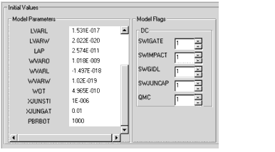
The Initialize menu contains a field to Set Initial Values to Circuit Defaults. Inside the Initial Values, Model Parameters section, enter process related parameters like the relative dielectric constant of the gate oxide, EPSROX. Advanced CMOS process generations are more and more making use of high-k gate dielectrics. Therefore, you can specify the relative dielectric constant of your process by changing EPSROX from 3.9 (default value for SiO2 gate dielectric). There are other process parameters to be specified on this folder, including electrical, process, or measured gate oxide thickness, TOXE, TOXP, TOXM; junction depth, doping concentrations, and sheet resistances. You will find a description of the model parameters and model flags for the BSIM4 model in Main Model Parameters and for the PSP model in Extraction of Parameters for the PSP Model. See also the manual from UC Berkeley Appendix A: "Complete Parameter List," for more details on model parameters as well as the PSP manual. Entering values into the fields and selecting the Save button starts a routine to check the values entered. This routine will flag an error message and change the color of the field whose parameter is given an unrealistic value. For example, if you enter -3 into the EPSROX field, this field will be marked with red color and remains red until the value is corrected.
You are able to add BSIM4/PSP parameters to the Initial Values by clicking Add Parameter inside the Initialize menu. You will be prompted with a list of BSIM4/PSP parameters. Select the parameters you would like to add and click OK. The parameters are added and you are able to enter initial values as desired.
The Model Flags section is used to set BSIM4/PSP model flags. The fields only enable settings as defined in the BSIM4/PSP model and are predefined to standard settings.
There is a field defining the symmetry of the drain and source areas. Check the appropriate box(es) if drain and source are processed using the same dose of implantation as well as the same geometry, and therefore the parameters are equal for drain and source areas.
Since most MOS processes use symmetric source and drain processing parameters, there is no need to extract the parameters for the bulk-source or bulk-drain diodes separately. Instead, check that the symmetry fields and the respective parameters are set equally.
Only for unsymmetrical processes, which could be modeled in BSIM4/PSP, the fields remain unchecked and a separate parameter set will be extracted for bulk-source and bulk-drain diodes.
Note
Binning
You will find some theory on binning inside Binning of Model Parameters. The following figure shows the Binning folder, used in binning model parameters. This folder is active only if the flag Generate Binning Model is checked, otherwise you will find an n/a sign next to the folder name. This flag is located on the Initialize folder under Generate Binning Model.
Figure 35 Part of the Binning Folder
Show Devices
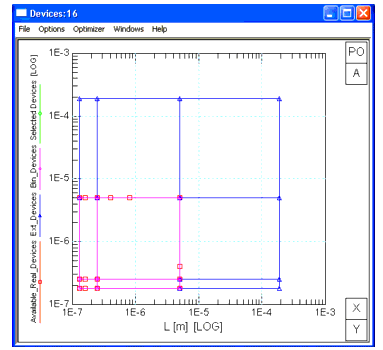
By selecting Binning > Show Devices, you will see a diagram using logarithmic axes of gate width over length, ranging from 0.1 to 100 microns showing the defined bin boundaries. Inside this diagram you will find markers for existing (measured) devices for this project.
Figure 36 Diagram of measured devices (red), extension devices (blue) and binned devices (magenta)
Set Bin
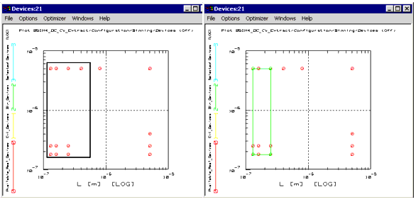
Select bin boundaries by using the displayed diagram, marking two adjacent corners of a rectangle representing the bin and choose Set Bin from the Binning menu. Be sure to include devices at every corner of your bin, otherwise you will get an error message stating that the selected bin is not rectangular. See the figures below for clarification.
- Binning areas:
- Left: Not correct, because not every corner of the marked rectangle has a measured device.
- Right: Correctly defined binning area.
- Left: Not correct, because not every corner of the marked rectangle has a measured device.
The selected binning areas are automatically entered into the form using a bin number and the geometries of the four corners for this bin.
Delete all Bins
Using this menu item, all bins are deleted from the graphic as well as the form.
Change Tolerance
The purpose of this menu item is to change a predefined tolerance for the binning areas. This tolerance is needed because of the definition of Binning Boundaries.
There are boundaries for each binning area: LMIN, LMAX, WMIN, WMAX. Those boundaries will be analyzed using Leff and Weff. If ![]() , a subcircuit will be used. This means, if a device with L=10µm is used and this is LMAX, then it is not possible to simulate this device using the binned model. This is due to the above mentioned region for the parameters:
, a subcircuit will be used. This means, if a device with L=10µm is used and this is LMAX, then it is not possible to simulate this device using the binned model. This is due to the above mentioned region for the parameters: ![]() . So if L = LMAX, the device does not fit into the binning boundaries (which require a value smaller than LMAX) and cannot be used for simulations.
. So if L = LMAX, the device does not fit into the binning boundaries (which require a value smaller than LMAX) and cannot be used for simulations.
Therefore, tolerances are implemented to correct for this error. You are able to change the predefined tolerance (0.01µm) to a value which suits your needs. The results within the measured and extracted areas will not be altered. But it is now possible to simulate devices having a gate length or width a little delta L or delta W outside the defined binning areas.
Add Extension
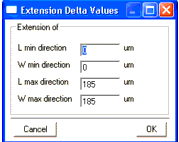
By choosing this button, you will get a form to enter Extension Delta Values like the one shown below.
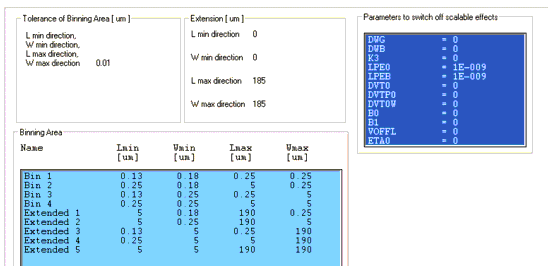
Figure 37 Extension values form
If the extension is not activated, certain simulators would not be able to simulate devices with L=Lmax or W=Wmax of certain bins. The extension delta values define the extensions from the measured devices. This means, you must set extension delta values Lmin and Wmin within the range of the minimal measured device, otherwise you will get an error message. In other words, if your minimal measured device uses a gate length of 0.15µm, the extension in Lmin direction must be set between 0 and 0.149µm. There is no limit for the extension in the Lmax and Wmax direction.
If you select one of the defined bins, the fields under Devices in Bin<No> will become green shaded and will show the name of the corner devices of this bin and the corner geometries, see Figure 35. At the same time, the diagram will show the selected bin boundaries in light blue color.
Delete Extension
You can delete the entered extensions by choosing the menu item Binning > Delete Extension button.
The field Parameters to switch off scalable effects is used to set which parameters use the scalable possibilities as defined inside the BSIM4/PSP model and which parameters are prevented from scalable modeling in BSIM4/PSP. All deselected parameters are using the extracted values, whereas all selected parameters (marked with blue background) are using default values for binning purposes. The parameters DWG and DWB are always off, therefore they cannot be de-selected.
DC Extract
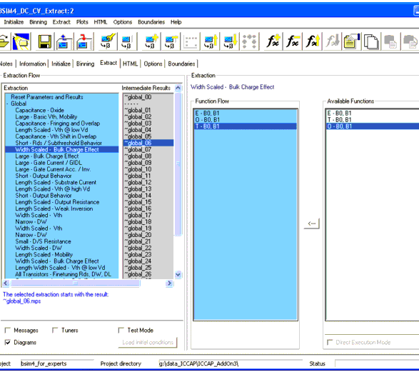
The next folder, Extract, defines the Extraction Flow for the devices. There is a standard extraction flow implemented, but you can change this flow if you find another one suiting your needs better than the default one.
The PSP model extraction flow is somewhat different, since it extracts local and global parameters in alternating steps, although the handling is the same. It is described in detail under Extraction of Parameters for the PSP Model.
You can also add custom extraction steps using a feature called Finetuning. See Finetune.
The folder shows fields named Extraction Flow, Extraction, Function Flow, and Available Functions. The Extraction Flow field shows the name for the selected extraction step. Under Function Flow, the functions used for the selected extraction flow are listed. The Available Functions field shows a list of functions to be used for a selected extraction flow. Mark the desired function and click the arrow in between the Function Flow and Available Functions fields to add the function to the flow list. The letters in front of the function name explain the extraction method used for this function: E represents extraction, O stands for optimization, and T for tuning.
The extraction list inside the field Extraction is organized into two main groups to provide a better overview when using a large number of steps or devices for extraction. This is done by introducing extraction groups for Global or Binning extraction, and hiding or expanding the list of extraction groups (for global extractions) respective to the list of devices (for binning extractions).
You can select the dependency from L, W, and P (L*W) for some of the parameters using the Extract > Edit Global Binning Parameter menu. A window opens up, where you can check parameters and dependencies to acknowledge during the global binning process.
Predefined extractions or optimizations for global binning parameters are not available. You can configure optimizations for global binning parameters in two ways:
| • | Generate a plot optimizer (see page 113) and invoke it in the group Finetuning inside the extraction flow. |
| • | Manually add global binning parameters to predefined optimizers. This change is saved as a user defined customization. |
You can set initial conditions for binning using the Extract > Extraction Flow > Initial Conditions menu or clicking the appropriate icon ![]() from the icon bar.
from the icon bar.
A window opens enabling you to configure full parameter sets for each device from other devices and add single parameters to this global binning extraction step from a list of parameters. You can select the intermediate results to use from a drop down list at the bottom of the Add Starting Parameters window that shows already extracted devices up to this stage of extractions. You are also able to delete single parameters from the list.
Global binning in this context means, there is the possibility to extract some parameters in a more global way. The device parameters are already extracted, now you are interested in geometrical influences on some parameters. Binning in the usual way recognizes dependencies on device length and width, represented through bins. Those bins represent ranges of lengths and widths of the devices. However, global binning uses no bins, but tries to extract the influences over length (parameter L), width (parameter W), and the product of L*W (parameter P). Using this feature, it is possible, for example, to represent a normally not on length and width depending parameter like VTH0 in a geometry dependent way through extraction over several different devices in this global binning approach!
Note
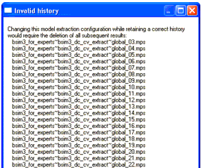
Using the menu Extract > Extraction Flow, there are buttons to Add or Delete Extractions from the flow. There are icons provided for these actions too. You will be prompted with a list of available extractions. Select one of the extraction steps and press Add on that form. If you have already extracted parameters, the Extraction Status field shows intermediate steps. This will show which results are being used for the selected extraction step. Now, if you Add or Delete, change the arrangement of the steps or reset to Defaults, the following extractions will become invalid because they are based on the results of the extraction immediately before them. Therefore, you will be warned before changes are made!
Arranging the flow is possible by using the Move Up or Move Down buttons below the Function Flow or by using the icons provided.
To extract parameters from one flow only: Select the desired flow under the Extraction Flow section in the left half of this folder and choose Extract >Single Extraction. Again, you will be warned before the selected extraction will be performed.
To go through the extraction process one step at a time, highlight the step and choose Extract > Step by Step Extraction. A dialog box may appear, prompting you for input.
| • | To automatically extract all parameters using the extraction flows listed under the Extraction Flow section, choose Extract > Automatic Extraction. The programmed Extraction Flow will be extracting all parameters defined in the active extraction flow list. The programmed extraction flow has to begin with the Reset Parameters step, otherwise you will get an error message. |
| • | In case you would start an extraction of some parameters after you already have extracted some other parameters, you are not able to start from the beginning without resetting all parameters, including the ones already extracted. To re-extract or to optimize one parameter after some other parameters are already extracted, simply add the desired step in the extraction flow list on a place further down the list. In that case, the extraction process uses the parameters already extracted during an earlier step in the extraction process and you overcome the reset parameter step. |
| • | All warnings and errors during the extraction process are written to the failure log, which is opened using the Extract > Failure Log menu item. |
The contents of the Failure Log window doesn't contain all the warnings written to the IC-CAP status window. Only the warnings and errors regarding parameter extraction are re-directed to the Failure Log.
Note
You can add several steps of the same extraction after each other. The extraction method selected in one step could be another one in a further extraction step. In other words, you are able to set the tuner option in one extraction step and the optimizer option in another step, probably when other parameters of influence have been extracted in between the steps.
| • | Change the function flow inside the Function Flow field using the Move Up or Move Down buttons below that section to move a selected extraction routine one step up or down. |
| • | The Default button restores the order of parameter extractions inside the Function Flow list as it was in the beginning of a project. |
| • | To delete an extraction from the Function Flow, choose Delete. |
You cannot delete the first (Reset Parameters) or the last (Save Parameters) extraction step inside an extraction flow.
Note
| • | Below the Extraction Flow field, check boxes enable you to Deactivate Tuners or to use the Test Mode without saving the extracted parameters. This mode is intended for you to test influences of some parameters on others without overwriting already extracted parameters from the selected step. You are able to use every *.mps file with every extraction step without saving and resetting parameters. |
You will notice the changing of colors on the Extraction Folder. This is a visual warning that intermediate results are not stored in this mode!
This feature makes it possible to test influences of any other *.mps file to compare extraction results.
Test mode starts with the last step taken in the flow. No results are overwritten or saved!
Note
| • | To export the extracted parameters during the defined extraction flow for the purpose of saving intermediate results, use Export Extraction under the Extract menu. You must specify the path and the name for the parameter file to be exported. Exported files will be packed into a .tar file using the project name as a file name and appending Export and a number to the extracted .tar file. (~project_name~Export_1, for example) |
| • | An item is provided under the Extract menu to Import Model Parameter Set, from an earlier project, for example. You will receive a warning message stating that importing parameters will overwrite the actual model parameters in IC-CAP. |
Select either a Project or, if existing, an exported .tar file for a specific project. In this case, you must select the project as well as the exported extractions. Then you will be able to select whether you would like to use all or specific parts of the saved extraction project components by de-activating the components not to be used (results, settings, boundaries and finetuning). If there are stored files, they will be shown under the Files section of this window.
This feature makes it possible to import any other *.mps file to compare results. But be careful, importing other parameter files will overwrite the actual parameters. Don't use this option during an extraction session with partly extracted parameters unless you've saved the work in progress!
Note
Interactive Extraction Mode
A new, powerful feature of IC-CAP and the BSIM Modeling Packages is the ability to display several plots in one window. It is called a Multiplot window. This feature is used when you enter the Interactive Extraction Mode. Either use the Extract menu or the interactive mode icon, ![]() , to invoke this mode.
, to invoke this mode.
The Interactive Extraction Mode opens a Multiplot window with a default number of plots shown. To the right of the interactive plot window, you can see three folders:
| • | Devices: This folder is used to select devices for extraction. You will find a list of devices as has been defined inside the measurement module, DC Transistor DUTs. Select one of the devices for extraction. |
| • | Extract: This folder shows one or more parameters to be extracted during this extraction step. You can select a device of your choice within the Devices folder or use the Default button (to be found on Devices) to accept the default transistor suggested by AdMOS. To the left of the Interactive Plot window, the extraction step and the extraction function for the selected step are shown. Start extraction by clicking Execute. The parameters are extracted and the plot window shows the simulated diagrams together with the measured ones. Now you are able to Store the results or continue the extraction process without storing intermediate results. Use the >-button to go on to the next step inside the extraction flow or extract all parameters of this step using the >>-button. |
| • | During extraction of some parameters inside the Extract folder, the Region Boundaries section is activated. Then you are able to select a specific extraction region by using Show button. The upper left of the plots is now showing a rectangle. This is the region where extraction takes place. You are able to change the predefined extraction area by opening a rectangle in Plot 0 (the upper left plot) using the left mouse button. A rectangle is shown. If you are satisfied with the selected area, use the right mouse button and select Add Region. The added rectangle now changes color and is used as the extraction region for this step. Remove the rectangle (the defined region is still valid) by using Hide. |
| • | The PEL button opens a window showing the default region calculation. This is done using the PEL language. Use this window to change the calculation by editing the values or changing the formulas used for calculation. Within this region calculation window, you are also able to reset any changes made using the Default button and/or to Accept and Show changes in Plot 0. Using OK, the selected or calculated region is accepted and used for this extraction step. |
| • | The Store button enables you to store intermediate results. This is useful for a what-if-scenario. Once you've stored parameters, the selection field to the right of the Store button enables you to select either the stored parameters or the results of the default step to be used for the next extraction step. Each parameter set you've stored will be given an extraction number using the sequence of the extraction. |
| • | If there is an optimizer step programmed during this extraction, the folder name changes from Extract to Optimize and there are fields to select optimizer features like Algorithm or Error. The Parameters field now enables you to enter parameter values manually by double clicking the parameter field and entering a value. You are also able to change boundaries of the parameters by using Autoset (the parameter value will be multiplied by 0.5 and 5 to determine the boundaries) or Reset (boundaries as have been defined inside IC-CAP model parameters window are used). Adopt will overwrite the standard IC-CAP values and the changed values are used for this extraction session. |
| • | The Parameters field of this folder enables you to add parameters to this step using the blank parameter field below the predefined parameters used in this step. If you enter a valid BSIM parameter and press enter, the value of this parameter as has been extracted so far will be shown in the middle column. |
| • | If you check the Save actual Optimizer Min/Max values check box, a new invocation of IC-CAP will use the changed boundaries, otherwise the standard values will be used again. |
| • | You can enter an exclamation mark (!) in front of a parameter to temporarily deactivate a parameter without removing it from the list. |
| • | Using the Tuner feature, this folder will change the name from Extract or Optimize to Parameter. The Parameters field of this folder has the same function as has been described for the optimizer above. |
| • | The third folder now changes from n/a to Tuner. It shows the parameter tuner sliders for interactive tuning. The results of changing the slider positions will be shown immediately inside the plots. Again, you are able to store results under predefined names. You can use the results of this step or go on without the results of the tuning step. |
Plots
The Plots menu Open Display item opens a Multiplot window used to display data.
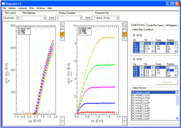
Configure the plot window using the Plot Layout pull-down menu to select a specific type of display layout. You can change between automatic and a predefined number of plot rows and columns or a user defined number of plots in the Plot window. Note, that the defined number of plots are opened only if an appropriate number of devices, outputs, or temperatures is selected. This means, if you manually set a plot display of 3x3 plots, select the IdVg-plot of one device at one temperature and one output, you will only see one plot! Choosing the Automatic plot layout displays the appropriate number of plots according to your selection!
To the right, you are able to select Devices, Bias Conditions, and Outputs to be plotted. Changes take place if you press Redisplay. Under the Plot menu of the Plot window, you can zoom in on a specific plot or get a full screen plot. You will be prompted for the plot to zoom to. This menu is also used to undo the display changes.
There is a pull-down menu, located below the top row of the multiplot window, named Display Template. It is used to store a set of displayed plots under a user specified name. This feature is intended to compare plots created with different extraction steps, for example. Arrange all plots you want to be stored, then press the save button and enter a name into the appearing window or accept the given one. To open an arrangement already saved, simply choose the one to be displayed from the Display Templates pull-down menu.
Folder Cycle Devices
Inside the Select Bias Condition area, select one or both diagram types: IdVg and/or IdVd. Then, click the desired voltages, temperatures, and outputs for the selected diagram types. You are able to mark one or more rows in each of the columns. To mark more than one voltage, temperature, or device, press and hold the left mouse button and select the items to be displayed.
The Select Device area shows the devices with the appropriate type of data according to your choice. For example, selecting a temperature other than room temperature will show only devices that are measured at those temperatures. Press Redisplay after you've made your choice.
A selection of more than one value of Vd or Temperature displays the chosen diagram (output) with a number of curves corresponding to your choice of Bias or Temperature.
Folder Cycle Plot Types
This folder enables you to choose different data representations or to compare the diagrams of different devices. For example, you can add a second y-axis to any plot, adding - let's say - the gate current to a diagram of the drain current vs. gate voltage.
If you selected a number of devices to be displayed using the same diagram for comparison and want to examine a curve that seems to be different from the others, you can zoom in on a plot. To zoom in on a plot, either select a plot and then Plots > Zoom Plot > Selected Plot from the menu of the multiplot window, or Zoom Plot or Full Page Plot and select one of the plots by number. The plots are numbered from top left to bottom right. The window changes in the Zoom Plot mode to one magnified plot and all other plots are displayed very small. In the Zoom Plot mode, you can jump to zoom another plot just by clicking the desired plot with the left mouse button. You can also select one curve of the chosen plot to be enhanced for reading voltages or currents from specific data points. Those currents and voltages are displayed above the diagram for the selected and marked data point.
Folder All Diagrams
Using this folder, you can display different plots to be compared or used for optimization. In contrast to the other folders of this window, you should define a Plot Layout first. If you select a 2x3-configuration, for example, you will get 6 empty plots inside the display area of the window. Click on one of those empty plots, open a menu by using the right mouse button and select Flexible Plot Configuration from this menu. Now you can select a predefined plot type from the All Diagrams folder and choose the desired voltages, axis settings, temperature, or devices to be displayed inside the selected plot. Using another plot, choose Transistor Capacitance > C oxide from the menu below the right mouse button, for example. This gives you the ability to mix plot types and devices in any configuration you'd like! For details, see the example provided in the following section.
Finetune
This feature enables you to add customized optimization steps. You can select one or more measured diagrams to create and save an extraction step in which to adjust certain parameters for a specific region of device behavior. This step can be inserted into the extraction flow at any desired step in the extraction procedure.
To use the finetuning feature, do the following:
| • | Open a Data Display. |
| • | Select the desired Plot Types, Devices, and Bias Conditions to be displayed. |
| • | Activate a diagram. |
| • | Activate this diagram for optimization (PO button to the right of the diagram). |
| • | Repeat the steps above for each plot you would like included in your finetuning step. |
| • | Open the Plot Optimizer (right mouse button: Optimizer > Open Optimizer). |
| • | From the parameter list of the Plot Optimizer, select the parameters you would like to finetune using the selected diagrams. Save your configuration. |
| • | Once the configuration has been stored, it will be present inside the BSIM4/PSP GUI extract folder under Available Functions in the Finetuning step and can be inserted into the Function Flow. |
The following is an example using this feature to extract the threshold voltage from two different types of plots.
| • | Open the Data Display (Menu: Plots > Open Display) and go to folder All Diagrams |
| • | Select a 2x1 plot layout from the Plot Layout menu |
| • | Select one of the plots, then use the right mouse button to access Flexible Plot Configuration. |
| • | Under the Plot Type pull-down menu in the All Diagrams folder, change plot type to IdVg: The measured devices together with the measurement voltages and temperatures appear. Select the desired voltages, temperatures, and devices then press Redisplay. The plot will be displayed! |
| • | Activate the second plot using the right mouse button to select Other Diagrams(Vth, Cap.,...) > Transistor Capacitance > C Overlap G-DS to display the overlap capacitance measured at the same voltages already selected for the first plot. |
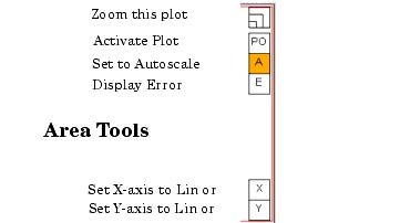
Now, activate Area Tools located under the Options menu. To the right of each of the plots, the area tools are displayed. These are tools to change the display of the plot to a zoomed condition, to change axis settings, to display relative or absolute errors, and to activate the Plot Optimizer. See the following figure:
| • | When you activate the Plot Optimizer, the color of the PO button changes to blue. At the same time, a blue rectangle appears around the plot window. Draw a rectangle around the area of the plot you'd like to use for optimization by pressing and holding the left mouse button. The rectangle appears in black color. Use the right mouse button to access the menu, choose Optimizer > Global Region > Add or simply press r on your keyboard. The rectangle's color changes to blue and the optimizer area is ready. |
| • | Select the appropriate area inside the second plot the same way. If the optimizer area in both plots appear with a blue rectangle, the plot optimizer is ready for use. |
| • | Open the Plot Optimizer window by choosing Optimize > Open Optimizer from the menu or simply press o on your keyboard. The optimizer window opens. |
| • | Inside the Plot Optimizer, select the parameters for use with this optimizing step. In our example, this would be VTH0. |
| • | Save the configuration by clicking Save in the Plot Optimizer region at the top of the Data Display window (not the Optimizer window!) and enter a name for this configuration. |
| • | Now, you can close the Data Display window and go to the Extract folder inside the BSIM4/PSP-GUI. |
| • | Press Extract > Extraction Flow > Add, choose to add the Finetuning Extraction step. This step will be inserted into the extraction flow. If you click on this finetuning extraction, the optimizing routine you just defined is available under the Available Functions list to the right of the Extract window and is ready to use. |
The Options menu enables you to add the calculated errors to the plot window, to set trace colors, or exchange the background color.
DC HTML
The folder HTML is used to generate a report file in HTML format. You can define a headline and comments for the report, specify the path to save the report, as well as the command to start the browser. You can also define the size of plots and the diagram background as it appears in the HTML report.
Generate HTML uses the project mps file (project_name~bsim*_dc_cv_extract.mps), not the loaded or imported one.
Note
If you use a path where an HTML project report already exists, you will get a warning. If the path doesn't exist, you will be a prompted to accept creation of the specified directory.
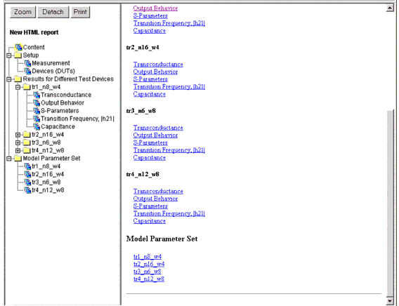
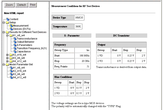
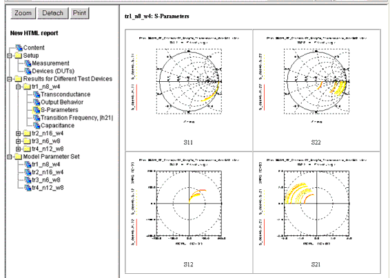
The following figures show part of a generated HTML report. This report could be published over the intranet for use inside your company or over the web for customer use.
DC Options
The folder Options lets you define some environmental conditions used in extraction.
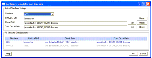
You can set the Simulator used by selecting the Change Simulator and Circuits button from the Options menu. You will see a window like the following one:
You can select which simulator to use from a pull-down list of ADS, SPICE3, Spectre, or HSPICE and you can select a SIMULATOR variable. You can also select the path to the appropriate circuit files respective the test circuit files. Usually, you will find those files in: ICCAP_ROOT/examples/model_files/mosfet/bsim3(or bsim4 or psp)/circuits/SIMULATOR/cir(tci).
If you would like to modify the standard circuit/test circuit files, be sure to copy the directory ICCAP_ROOT/examples/model_files/bsim3(or bsim4 or psp)/circuits/<SIMULATOR> and change the files inside the copied directory, not the original ones.
Note
There are predefined values for the variables. You can change those variables or accept the values.
Using those variables you can define a minimum usable current for extraction. The purpose of these variables is to cut out noisy current measurements by defining the lower limit of currents used for extraction of different parameters.
DC Boundaries
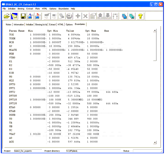
The folder Boundaries is intended to set optimizer boundaries for some parameters. Since the parameters differ between BSIM3 and BSIM4/PSP, there are little differences in the look of the boundaries folders.
Boundaries
Figure 40 Boundary settings for the BSIM Modeling Packages
On the left side, you can see the parameters to be optimized. The following columns display the minimum for the named parameter (the parameter's reasonable physical minimum), an optimizer minimum and maximum column, followed by the parameter's maximum, if a reasonable one exists. The white fields let you enter optimizer settings fitting your process needs. You can Save these settings for future extractions using the File menu. You can restore boundaries by clicking Boundaries > Set to Default from the menu.
The parameters and min/max values are taken from the IC-CAP Model Parameters folder.
