Print version of this Book (PDF file)
Extraction of Parameters for the RF Models
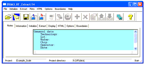
Start extraction of RF parameters for the BSIM3 or BSIM4/PSP models by clicking the appropriate extract model to open the graphic user interface (GUI) you are already familiar with. The tasks are separated on subfolders for easy handling. Some of the folders are using the same look as in the DC Extraction part of the BSIM3 and BSIM4/PSP Modeling Tools.
The top row menus are described in DC and CV Measurement of MOSFET's for the MOS Models.
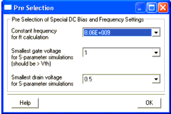
As soon as you click File > Open, the PreSelection dialog box opens, prompting you for some basic definitions for parameter extraction.
Within this window, select some DC and frequency settings for the extraction process.
Transit frequency fT of a transistor is being calculated using the standard procedure of measuring the gain at a predefined frequency and extrapolating fT from the gain-bandwidth product of one. Enter the frequency to be used for extraction into the PreSelection window. Only frequencies defined in the measurement section using the Measurement Conditions folder are allowed. Inside this folder you've entered Start and Stop Frequency as well as Number of Frequencies to be measured. Frequency sweep divided by number of frequency points results in specific frequencies to be measured. Those are the frequencies you are able to select as constant frequency for fT calculation. Be aware of the network analyzer's accuracy at lower frequencies when selecting the calculation frequency.
You can further specify the smallest gate and drain voltages to be used for S-parameter simulations. Choose the minimum gate voltage to be greater than the threshold voltage to ensure that the device is operating inside the active region. Otherwise, there will be a problem in extracting Rout. This resistance is very high if the transistor is turned off, resulting in large errors during extraction. Measurement is being carried out at gate and drain voltages from zero volts upward, but parameter extraction will lead to erroneous values.
RF Extract Notes
The Notes folder has been described already. See Project Notes.
RF Extract Information
The second folder, Information, has the same look and function as the one in DC Extraction. See DC Information.
RF Extract Initialize
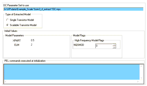
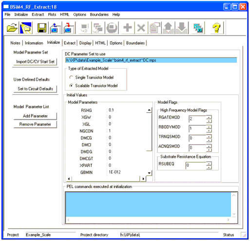
The folder Initialize is used to set initial values during extraction for process and geometric parameters as well as model flags. There are differences in initializing BSIM3 and BSIM4/PSP models. The following figures show the initialization folders of each of the models.
BSIM3 — Initialize
Figure 41 Initialize folder for the BSIM3 model
BSIM4/PSP — Initialize
Figure 42 Initialize folder for the BSIM4 model
The Initialize folders contain sections to enter PEL commands to be executed at initialization of the extraction process.
Model Parameter Sets
From the Initialize menu, you can Import DC/CV Start Set to be used for RF extraction. You get a list of existing *.mps files for selection. A selected *.mps file will be copied into the RF project directory. This action will set parameter values extracted from DC/CV measurements as starting points for RF extraction. Since the devices measured for RF extraction are very compact multifinger transistors due to design requirements (and also to enhance accuracy through reducing measurement noise during network analyzer measurements), their parameters differ from the ones extracted from DC measurements. To get results consistent for the process—not only for the actual measured device—the extraction of RF relevant parameters must start with initial parameter start points to fit the S-parameters at low frequencies. Therefore, using parameters extracted during the DC extraction process are used to give start points of good accuracy for the RF extraction process.
The path and filename of the selected start set will be shown on blue background.
Set parameters to circuit default values: Choosing the Set to Circuit Default Values menu item restores the defaults.
You can Add or Remove Parameters from the Initial Values list in the middle of the Initialize folder using the Initialize menu.
Select the type of model to be extracted. There are two selections possible: Single or Scalable Transistor Model. For a detailed explanation, see Single Transistor Model or Fully Scalable Device.
You can set initial parameter values manually. To do so, enter the desired values into the parameter fields provided for several parameters.
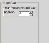
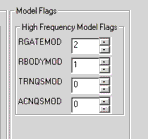
Figure 43 High Frequency Model Flag Selection for the BSIM3 (left) and for the BSIM4 (right) RF models (Part of Initialize Folder)
The BSIM3 model only uses one flag for RF modeling—the NQSMOD flag (non-quasi-static model, see Non-Quasi-Static Model Parameters).
Set high frequency Model Flags for the extraction of BSIM4/PSP parameters by using the arrows provided to change the flag value. The process is limited to allowed flag values of the respective RF model.
The flags can have values as listed in the following table.
RGATEMOD
[Page 8-8]0 (no gate resistance)
1 (constant gate resistance)
2 (variable gate resistance)
3 (two gate resistances, overlap capacitance current will not pass through intrinsic input resistance)Gate resistance model selector
RBODYMOD
[Page 8-9]0 (no substrate resistance network)
1 (five substrate resistors are present)Substrate resistance network model selector
TRNQSMOD
[Page 8-3]0 (charge deficit NQS model is off)
1 (charge deficit NQS model is on)Transient Non-Quasi-Static (NQS) model selector
ACNQSMOD
[Page 8-5]0 (small signal AC charge deficit NQS model is off)
1 (small signal AC charge deficit NQS model is on)AC small-signal Non-Quasi-Static model selector
Note [Page 8-X] refers to the page numbers of the BSIM4.3.0 Manual from UC Berkeley [1]
RF Extract
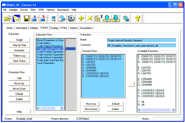
Within this folder, you define the extraction process for the parameters of the devices. There is a standard extraction flow implemented, but you can change this flow if you find another one suits your needs better than the default flow.
| • | To extract parameters from one flow: Select the desired flow under the Extraction Flow section of this folder and choose the Single button. Only the selected extraction will be performed. The status of extraction is visible in the status field. This field shows a `-' if extraction of this parameters is not completed yet or `done' if the parameters from this step are extracted. |
| • | To go through the extraction process one step at a time, highlight the step then choose Step by Step. A dialog box may appear, prompting you for input. |
| • | To automatically extract all parameters using the extraction flows listed under the Extraction Flow section: Choose Automatic. The programmed extraction flow will be extracting all parameters defined in the active extraction flow. |
| • | All warnings and errors during the extraction process are written to the failure log, which is opened using the Failure Log button. |
If you would like to clear the status of extraction, use Clear Status.
| • | You can add steps to the extraction flow by clicking the Add button on the left side of the folder under the section Extraction Flow. You will be prompted for an extraction to add. Select the desired extraction and choose Add on the Add Extraction folder. |
| • | Change the flow of extraction by using the Move Up or Move Down buttons to move a selected extraction routine one step up or down. |
| • | The Default button restores the order of parameter extraction as it was in the beginning of a project. |
| • | To delete a step: Choose the Delete button. |
You cannot delete the first (Reset Parameters) and the last (Save Parameters) step inside an extraction flow.
Note
| • | To export the extracted parameters: The step Save Parameters inside the Extraction Flow informs you of the path and name for the saved .mps or .lib file. |
On the right side of the Extract folder, you will find a field named Extraction.
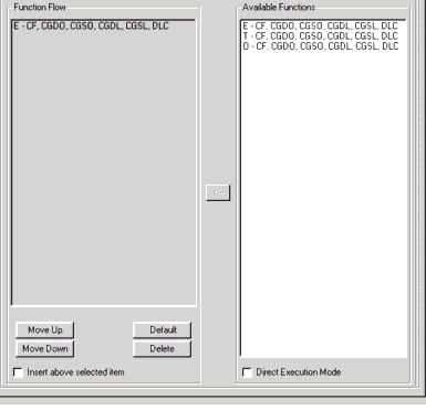
This field shows the name of the extraction as well as name and path of the transform used in this extraction step. There is a field, Function Flow, which is used to set the flow of extraction steps. Select the desired function out of the list found under Available Functions by selecting the function and clicking the arrow in between the Function Flow and the Available Functions fields. Arranging the functions inside the function flow is done using the buttons provided below the Function Flow field.
Under Available Functions you will find in the example above three functions for this function flow. The first function is an extraction step (E), the second one uses the tuner (T), the third one uses the optimizer (O).
RF Extract Display
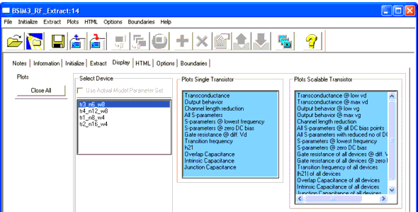
Within this folder, you will find fields to select plots for display.
There are three fields to select models for display on this folder:
Select Device: Use Actual Model Parameter Set or choose one of the buttons to the left of the transistors name for plots to be displayed.
Open plots for the selected transistor by clicking the name of the plot inside the Plots Single Transistor field on the folder.
Open plots for scalable transistor models by clicking the name of the desired plots inside the Plots Scalable Transistor field on this folder.
You can only choose a plot for the extracted model that was selected in the field Type of Extracted Model on the Initialize folder. Plots inside the other fields are not selectable.
Note
Each plot is opened in a new window. Close all windows by using the Close All button on the right side of the Display folder or close single windows using the Close icon inside the appropriate window.
RF Extract HTML
This folder helps you to prepare a report file in HTML format to be displayed using an internet browser.
Since this folder is the same as in the DC Extraction section, see DC HTML for details.
RF Extract Options
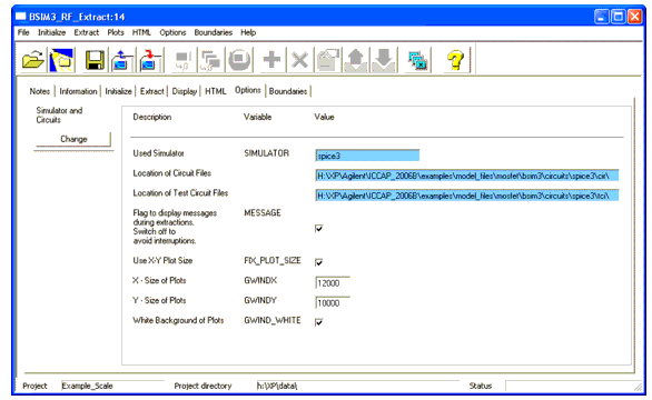
This folder is used to set variables for the extraction process and options for plots to be displayed.
The Simulator variable field and the paths to circuit and test circuit files have a blue background. You cannot change those field entries directly. Instead, you have to choose the Simulator and Circuits Change button to set another target simulator as well as paths to circuit and test circuit files. If you use your own circuit files, it is recommended to copy the entire examples directory into a directory where you have write access and set the path according to your situation. You will find the path to the examples directory on the options folder! If you are satisfied with the default settings or to use as a starting point, just leave the path entries as provided.
There is a field to enter the printer command for printing the plots (see the notes on printing in the section DC and CV Measurement of MOSFET's for the MOS Models).
If you want to change the plot window size, choose Use X-Y Plot Size: Fixed_Plot_Size and enter the desired X and Y size into the respective fields. You are able to change the background color of the plot window from black to white by activating the field: White background of plots.
Circuit Files
The circuit files are located in:
 ICCAP_ROOT/example/model_files/mosfet/bsim3(or
bsim4 or psp)/circuits
You will find subdirectories below the circuits directory for each supported simulator (hpeesofsim, hspice, spectre, spice3). Each directory contains a circuit (cir) as well as a test circuit (tci) directory, which contain the circuit files using the appropriate simulator syntax.
RF Extract Boundaries
The Boundaries folder is the same as the one in DC Extraction. For details, see DC Boundaries.
