Defining DUT Options
IC-CAP models usually contain several DUTs. DUTs contain groups of setups that have a similar physical connection to the device. In addition to setups, each DUT contains its own variables, parameters and test circuit. If two setups require differences in either of these areas, you must define different DUTs for each.
Before you can measure a device, you must make any needed changes to the DUT options.
To view the DUT options and make a device active, select the DUTs-Setups folder. Then select the DUT.
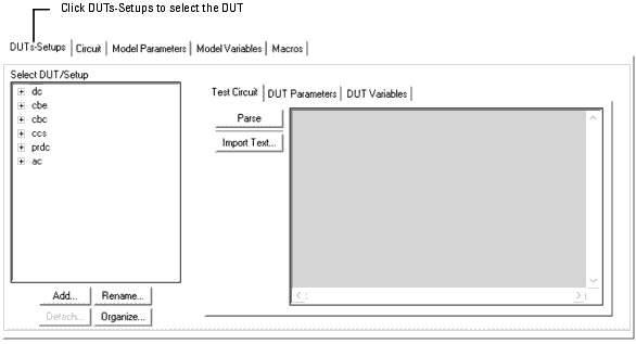
Adding a DUT
To add a DUT:
| 1 |
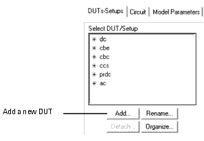
In the DUTs-Setups folder, click Add. |
| 2 |
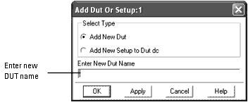
In the dialog box that opens, select Add New DUT. |
| 3 |
In the Enter New DUT Name field, type a name for the new DUT and click OK. |
See also: Organizing DUTs
Deleting a DUT
To delete a DUT:
| 1 |
In the DUTs-Setups folder, select the DUT you want to delete. |
| 2 |
Select Edit > Cut DUT, or click Cut on the toolbar.
|
|
Note
|
|
|
|
|
You can also delete a DUT by right-clicking on the DUT to view its pop-up menu. Then select Edit > Cut.
|
|
See also: Organizing DUTs
Organizing DUTs
To move a DUT in the list:
| 1 |
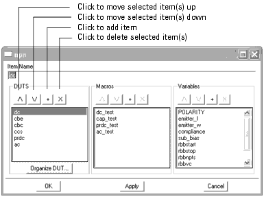
Select Tools > Organize Model from the Model window to display the following dialog box: |
| 2 |
From this dialog box, select one or more DUTs. |
| 3 |
Above the selected DUT(s), click the move up  icon to move the selected DUT(s) up in the list, or click the move down
  icon to move the selected DUT(s) down in the list. Each click moves the selected DUT(s) one position.
 |
To add a DUT:
| 1 |
Choose where you want to add the DUT in the list: |
| |
• |
Select a DUT if you want to add a DUT after that position. |
| |
• |
Do not select a DUT if you want to add a DUT to the first position. |
| 2 |
Click the plus  icon.
icon. |
| 3 |
A new DUT named Untitled is added. Type the desired name in the Item Name field then select the Enter key. |
To delete DUTs:
| 1 |
Select one or more DUTs. |
| 2 |
Click the delete  icon.
icon. |
To apply you changes and leave the dialog box open, select the Apply button.
To apply your changes and close the dialog box, select the OK button.
To close the dialog box without making changes, click the Cancel button.
See also: Organizing DUTs and Setups
Specifying a Test Circuit
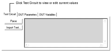
Typically, the test circuit is empty. However, you can use the Test Circuit folder to attach additional circuitry between the device or circuit being modeled and the measurement hardware. For example, an OpAmp model may need to be connected in different configurations for different measurements.
When a test circuit is defined for a DUT, the parameters in the test circuit appear in the DUT parameters folder. For complete information on defining Test Circuits, refer to Chapter 6, "Simulating."
To specify a test circuit:
| 1 |
In the DUTs-Setups folder, select the DUT. Then select Test Circuit. |
| 2 |
Edit the existing test circuit by typing over the existing values or enter new test circuit data in the window. |
|
Note
|
|
|
|
|
You can copy a test circuit from an existing model. Open the model and select the DUT you want to copy. Select the Test Circuit folder. Select Edit > Copy DUT/Test Circuit. In the selection dialog box, choose Selected Test Circuit. Then select Edit > Copy. In the new Model window, select the Test Circuit folder. Select Edit > Paste Test Circuit.
|
|
Defining DUT Parameters
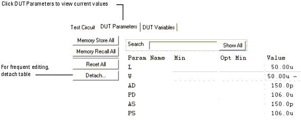
The DUT parameters may take on different values in each DUT. For example, the DC characterization of the MOSFET requires measurements on three DUTs (large, narrow, and short). Each of these DUTs have different specifications for channel length (L) and width (W). You can specify these different values in the DUT Parameters folder. In addition, you can set limits by defining minimum and maximum values for each parameter. If a parameter value is outside its limits, it will be clamped to its minimum or maximum value.
To specify DUT parameters:
| 1 |
In the DUTs-Setups folder, select the DUT. Then select DUT Parameters. |
| 2 |
Select the Param Name Value field and edit the DUT parameters for the device being measured. |
| 3 |
Optionally, select the Param Name Min field and set minimum values for the DUT parameters. |
| 4 |
Optionally, select the Param Name Max field and set maximum values for the DUT parameters. |
| 5 |
Select an action from the following: |
| |
• |
To temporarily store the current set of parameter values, click Memory Store All. |
| |
• |
To recall stored parameter values, click Memory Recall All. |
| |
• |
To reset the default values specified in the circuit definition, click Reset All. |
|
Note
|
|
|
|
|
You can copy DUT parameters from an existing model. Open the model and select the DUT you want to copy. Select the DUT Parameters folder. Select Edit > Copy DUT/Device Parameter Set. In the selection dialog box, choose Selected Device Parameter Set. In the new Model window, select the DUT Parameters folder. Select Edit > Paste Device Parameter Set.
|
|
Defining DUT Variables
You can define variables that are accessible only to the DUT or its components in the DUT Variables folder. After you have defined the variables, you can reuse these definitions by applying the Import and Export commands.
To specify new DUT variables:
| 1 |
In the DUTs-Setups folder, select the DUT. Then select DUT Variables. |

| 2 |
Enter the names and values for all DUT variables: |
| |
• |
Click the first empty row in the Name field and type a name for the variable. |
| |
• |
Press Tab to move to the Value field. Type a value for the variable. |
| |
• |
Press Enter to accept the value and open another row. |
|
Note
|
|
|
|
|
To view system defaults from the DUT Variables folder, select the  button.
|
|
|
Note
|
|
|
|
|
You can copy DUT variables from an existing model. Open the model and select the DUT you want to copy. Select the DUT Variables folder. Select Edit > Copy DUT/ Variable Table. In the selection dialog box, choose Selected Variable Table. In the new Model window, select the DUT Variables folder. Select Edit > Paste Variable Table.
|
|
|
![]() button.
button.


