Print version of this Book (PDF file)
Binning of PSP Models
Binning Rules in PSP
The PSP Model (Version 102) has 3 different binning rules with a fixed assignment to certain parameters:
| • | Type I: |
| • | Type II: |
| • | Type III: |
Channel length reduction LE, WE are calculated as:
The parameter LAP in Equation 2 is defined as the effective channel length reduction, the parameter WOT in Equation 3 as the effective channel width reduction due to lateral diffusion of channel stop implant ions.
In contrast to BSIM4, the model parameters of the binned PSP model originate from 2 different sources: The local and the global model. The table below describes the source of the final binning parameters and whether an extension (PO, PL, PW, PLW) is to be added.
Generation Process for a Binned Simulation Model
The PSP Modeling Package comes with an example model file called psp_binning. This model file shows the typical extraction flow to generate a binned simulation model.
If you create a binned model, make sure the Generate Binning Model flag in the Initialize folder is marked and the bins are set correctly to include the available devices into the defined bins. See details in Binning.
When you open the example, you can see that the Generate Binning Model marker on the Initialize folder is activated and the bins are set according to the devices available.
Binning Extraction Flow
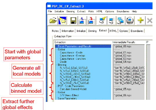
The general extraction flow for a binned project is shown in the following screenshot. The extraction flow follows the general rules as previously described (see Extraction of Parameters for the PSP Model). After extracting global model parameters, local parameters for the devices selected inside the different bins during initialization are extracted. Then, the calculation of the binned model is done, before global parameters like the ones used for Stress Effect modeling are handled.
Furthermore, the extraction of the local models should be done in a special order to preserve the correct nature of a binned PSP model. The order is as follows:
| • | Long/Wide device |
| • | Short/Wide device |
| • | all other devices |
The sequence shown in the following figure must be followed, since some of the necessary parameters are to be extracted from the Long/Wide or the Short/Wide device only and are used for all other devices.
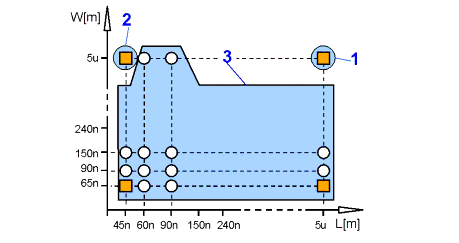
Figure 55 Extraction order to create a binned model
Figure 56 Extraction step: Calculate Binning Model
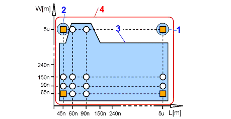
To correctly extract the binning model parameters, you must select which intermediate result (which preceding extraction step) to use for the actual step. For the Long/Wide device, the preceding step is a step from the global extraction (this is the default). For all other devices, the results must be out of the Binning main group, otherwise, the parameters extracted are not correct!
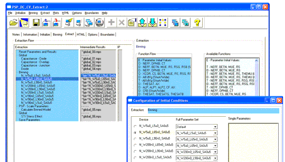
To set the steps, use the Initial Conditions window, either from the pull-down menu Extract > Extraction Flow > Initial Conditions or using the appropriate icon. The following figure explains this in more detail.
Figure 57 Configuration of Initial Conditions for devices to be binned
Inside the Configuration of Initial Conditions window, you can select the Full Parameter Set appropriate for this device by using the pull-down menu to the right of each device.
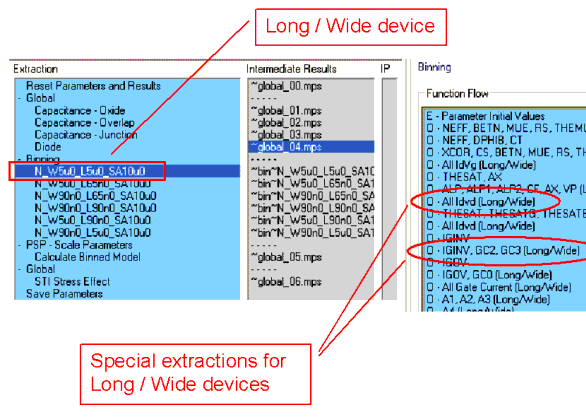
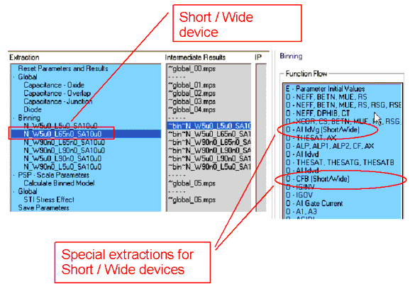
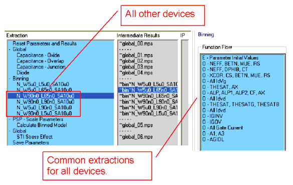
There is a tailored function flow adopted to the requirements of Binning, as shown in the following three screenshots. The first one shows the Function Flow for the Long/Wide device, the second one for the Short/Wide device. Special functions for these devices are marked with a comment in brackets behind the parameter name, showing for which device this function is used.
When selecting the Long/Wide device, the Function Flow to the right of the Extract folder shows special optimizations for the Long/Wide device.
In this case, the Short/Wide device was selected and the Function Flow shows optimizations especially for Short/Wide devices.
The extraction Calculate Binned Model creates a binned circuit, which depends on the devices selected in bins. As soon as this circuit is created, it is loaded inside the extraction flow after that function and the HTML report is created using the circuit.
If you change the position inside the extraction flow to one created before binning was started (for example, in using the test mode) at that position the regular circuit (not the binned one) will be loaded.
