SRC/draw.c File Reference
#include <stdio.h>#include <string.h>#include <math.h>#include "util.h"#include "vpr_types.h"#include "vpr_utils.h"#include "globals.h"#include "graphics.h"#include "path_delay.h"#include "draw.h"#include <assert.h>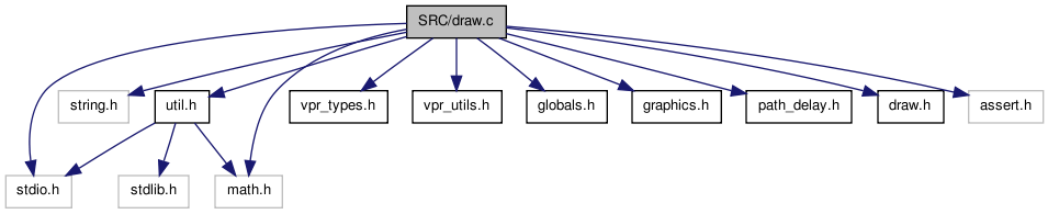
Go to the source code of this file.
Defines | |
| #define | MAX_BLOCK_COLOURS 5 |
Enumerations | |
| enum | e_draw_rr_toggle { DRAW_NO_RR = 0, DRAW_ALL_RR, DRAW_ALL_BUT_BUFFERS_RR, DRAW_NODES_AND_SBOX_RR, DRAW_NODES_RR, DRAW_RR_TOGGLE_MAX } |
| enum | e_draw_net_type { ALL_NETS, HIGHLIGHTED } |
| enum | e_edge_dir { FROM_X_TO_Y, FROM_Y_TO_X } |
Functions | |
| static enum color_types *static block_color void | toggle_nets (void(*drawscreen)(void)) |
| static void | toggle_rr (void(*drawscreen)(void)) |
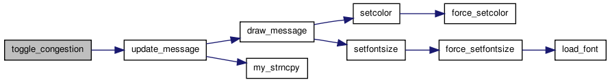
| static void | toggle_congestion (void(*drawscreen)(void)) |
| static void | highlight_crit_path (void(*drawscreen_ptr)(void)) |
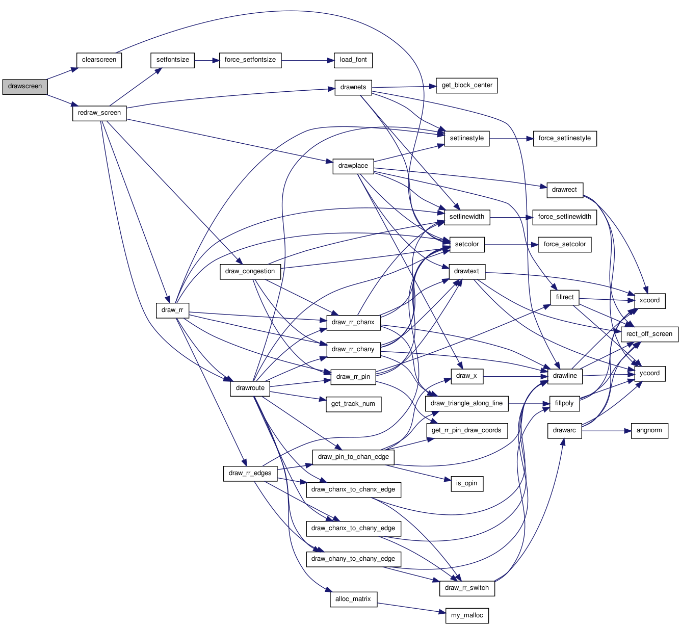
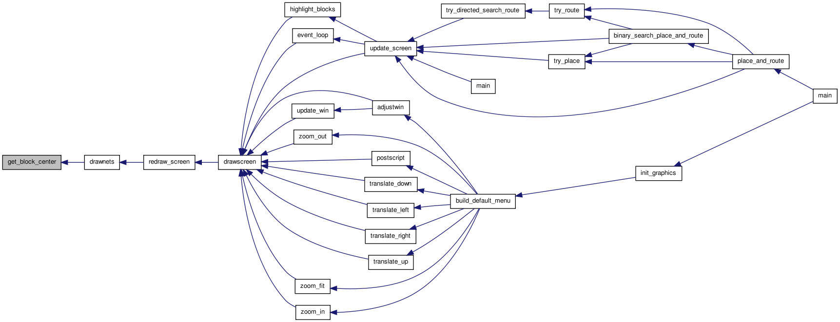
| static void | drawscreen (void) |
| static void | redraw_screen (void) |
| static void | drawplace (void) |
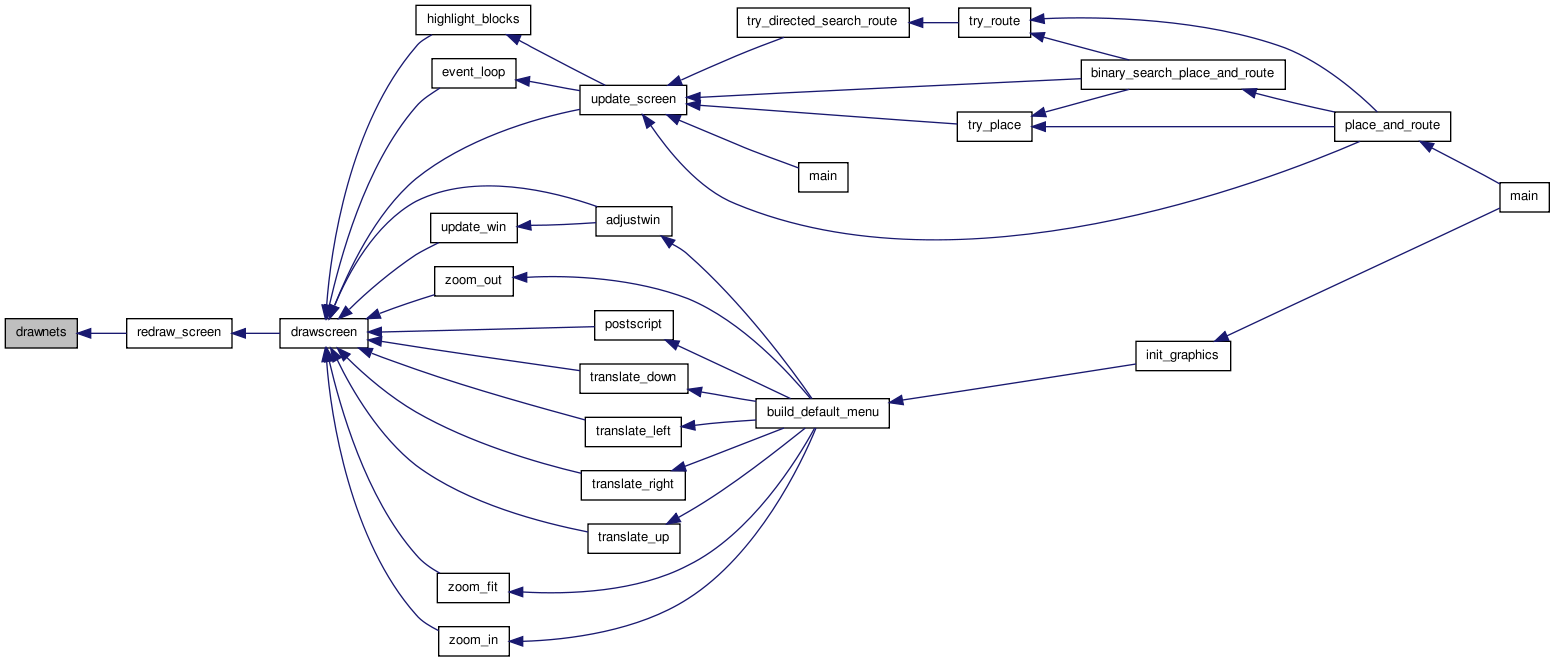
| static void | drawnets (void) |
| static void | drawroute (enum e_draw_net_type draw_net_type) |
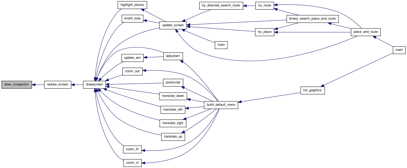
| static void | draw_congestion (void) |
| static void | highlight_blocks (float x, float y) |
| static void | get_block_center (int bnum, float *x, float *y) |
| static void | deselect_all (void) |
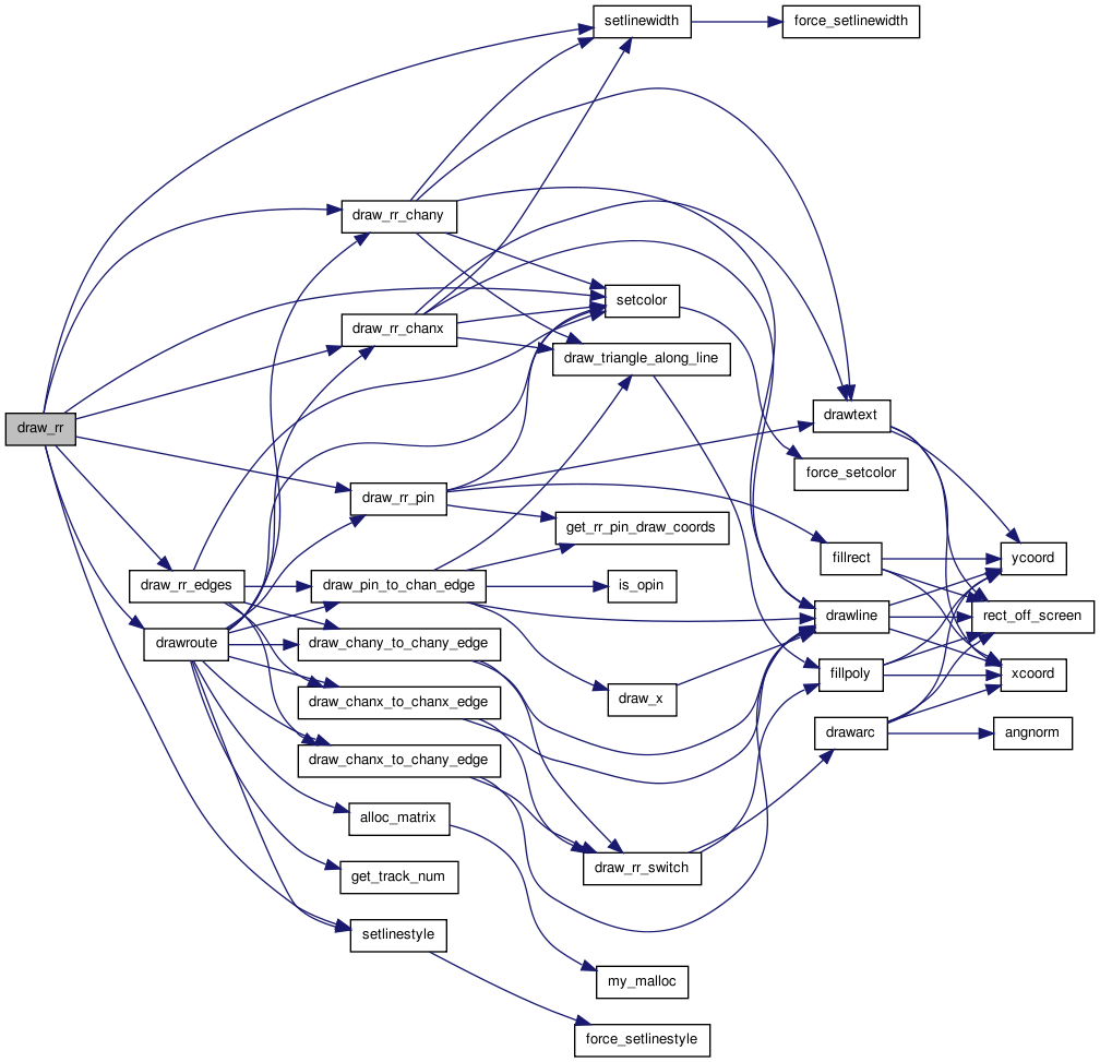
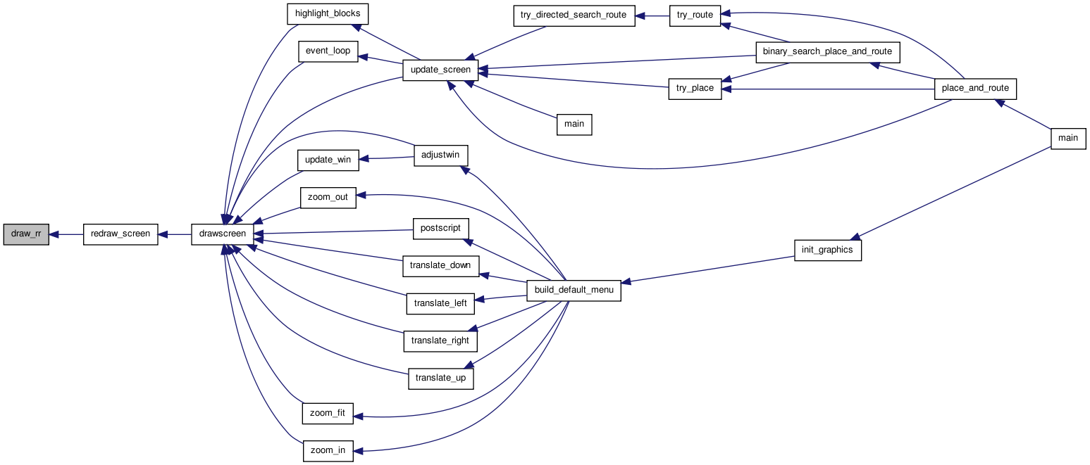
| static void | draw_rr (void) |
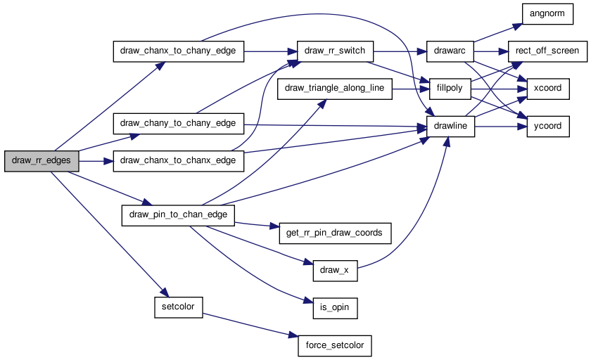
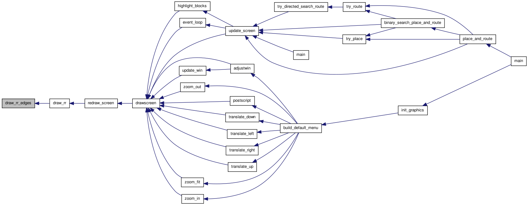
| static void | draw_rr_edges (int from_node) |
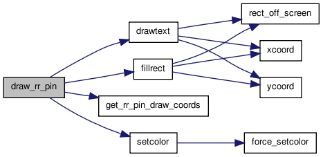
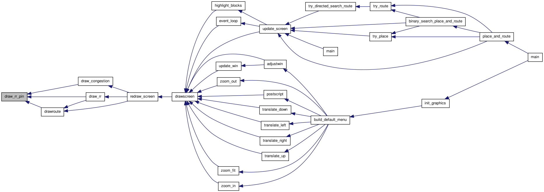
| static void | draw_rr_pin (int inode, enum color_types color) |
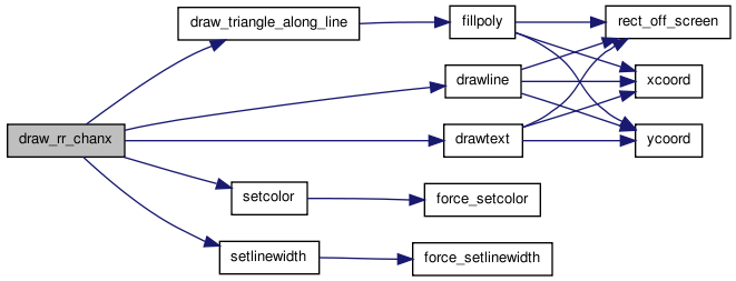
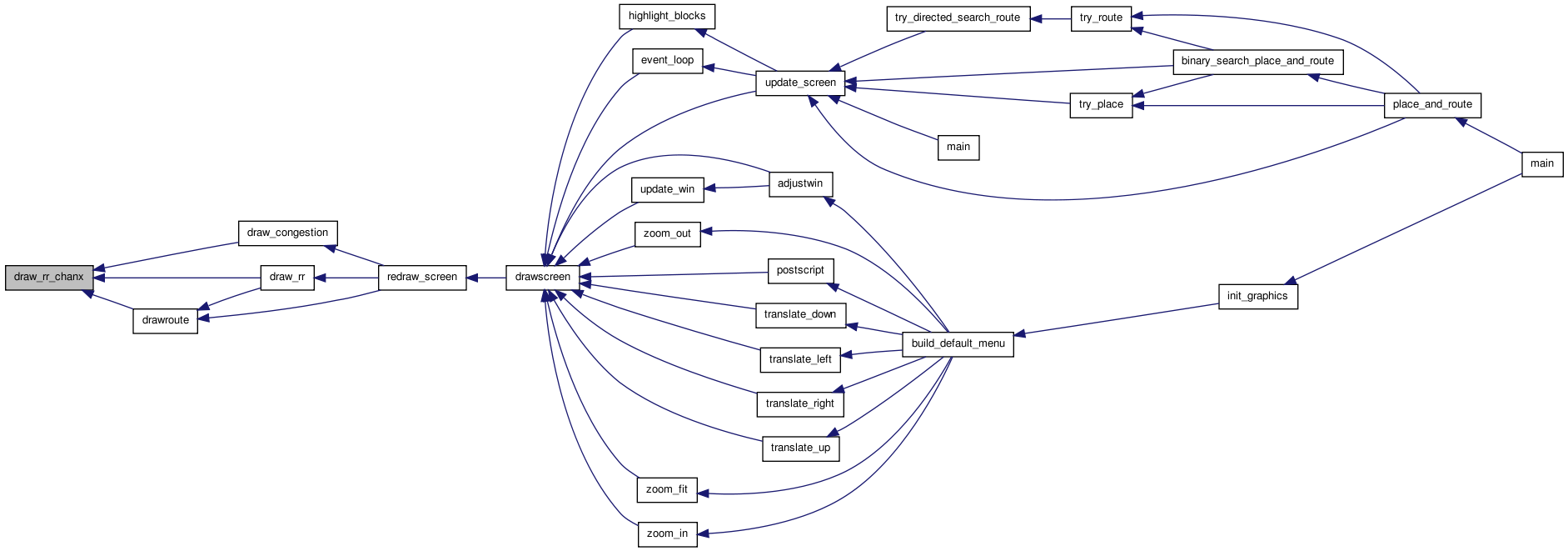
| static void | draw_rr_chanx (int inode, int itrack) |
| static void | draw_rr_chany (int inode, int itrack) |
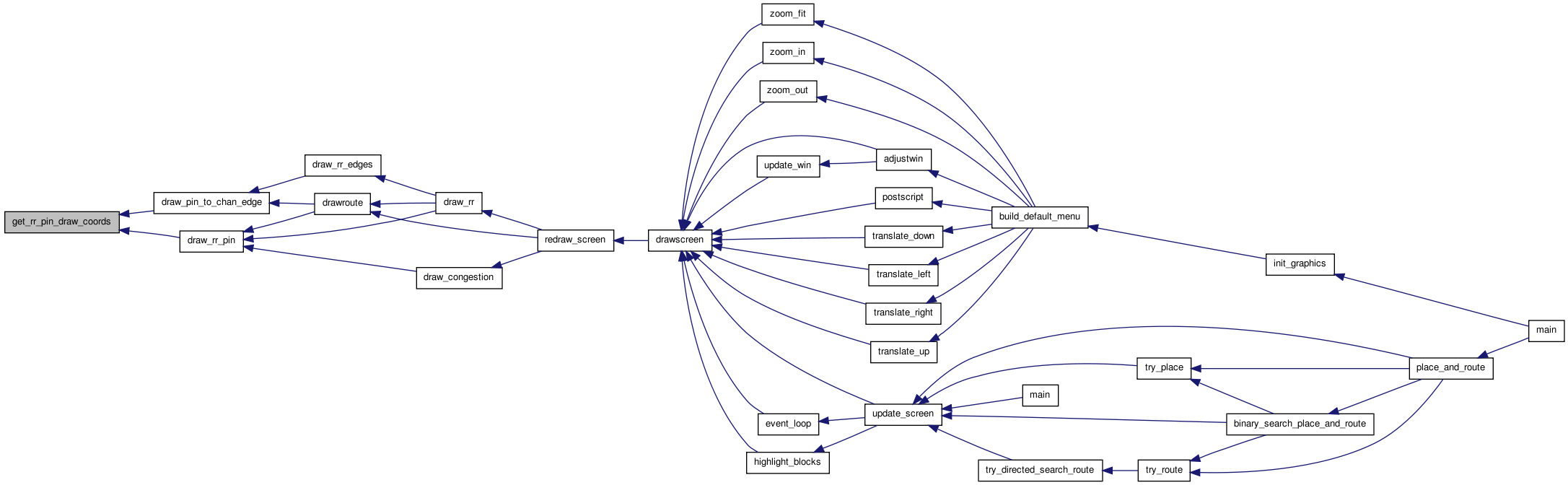
| static void | get_rr_pin_draw_coords (int inode, int iside, int ioff, float *xcen, float *ycen) |
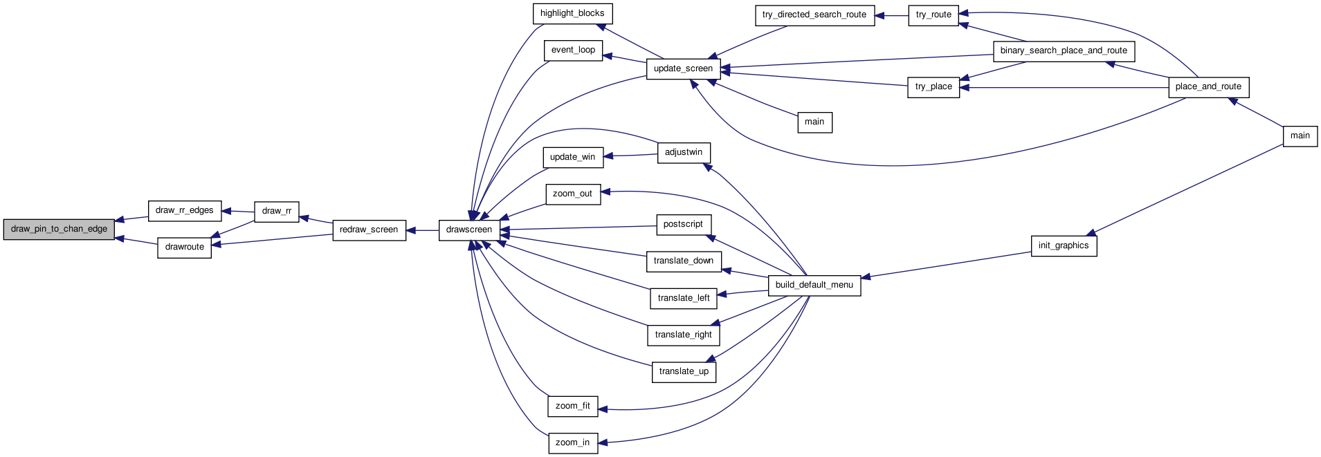
| static void | draw_pin_to_chan_edge (int pin_node, int chan_node) |
| static void | draw_x (float x, float y, float size) |
| static void | draw_chany_to_chany_edge (int from_node, int from_track, int to_node, int to_track, short switch_type) |
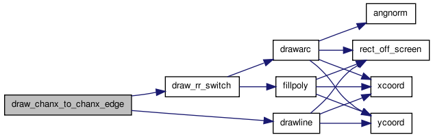
| static void | draw_chanx_to_chanx_edge (int from_node, int from_track, int to_node, int to_track, short switch_type) |
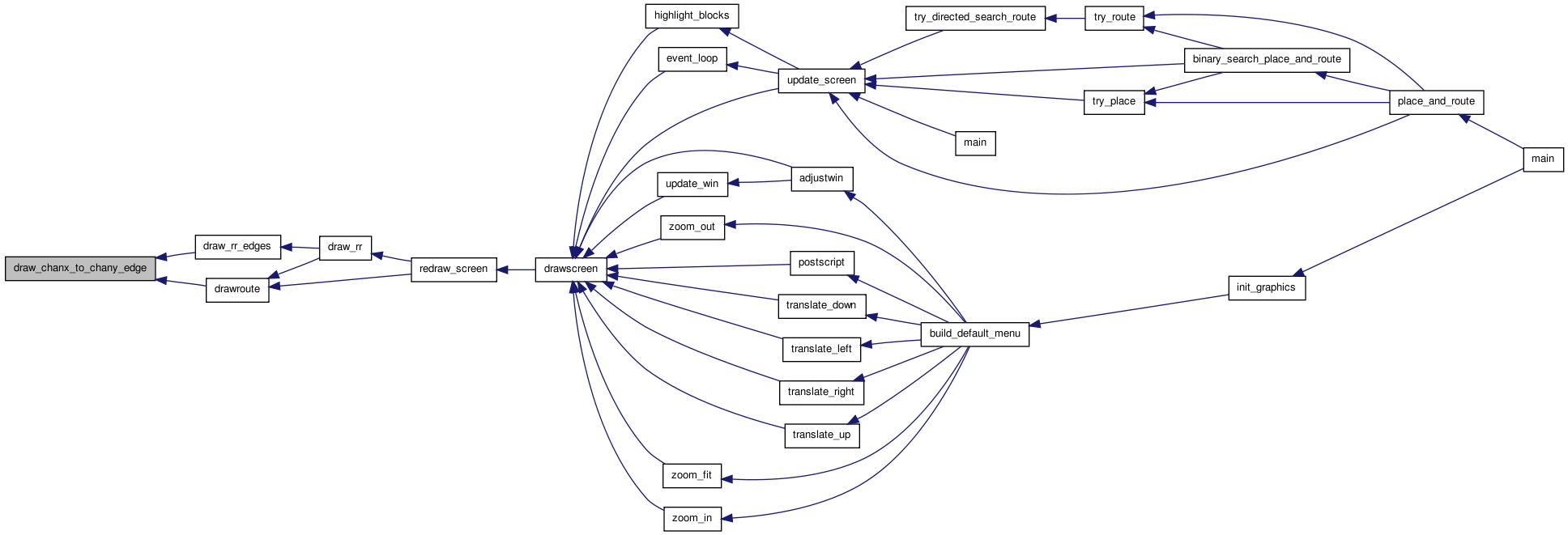
| static void | draw_chanx_to_chany_edge (int chanx_node, int chanx_track, int chany_node, int chany_track, enum e_edge_dir edge_dir, short switch_type) |
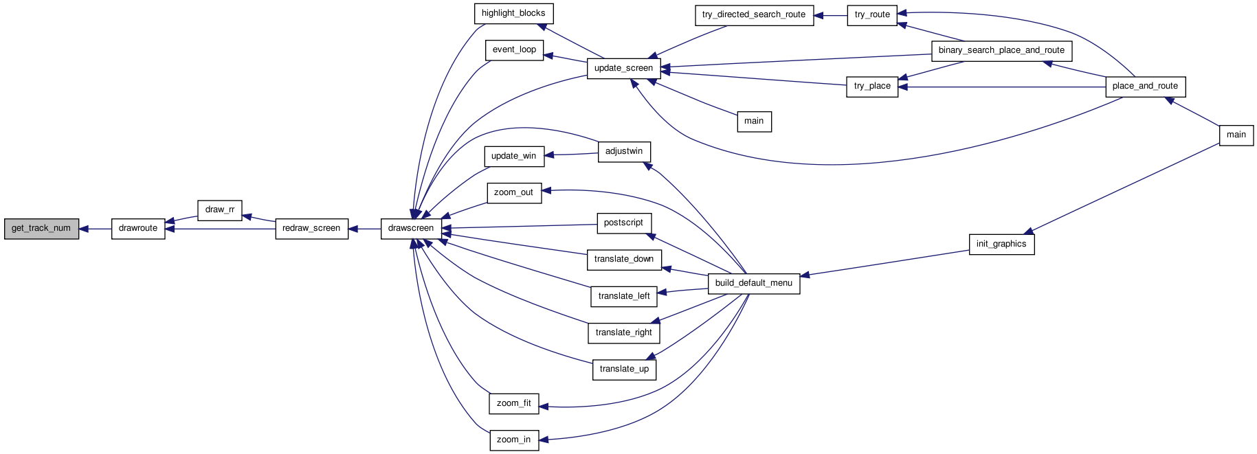
| static int | get_track_num (int inode, int **chanx_track, int **chany_track) |
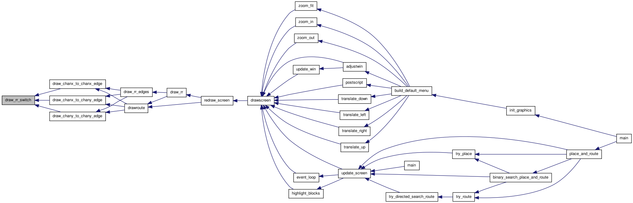
| static void | draw_rr_switch (float from_x, float from_y, float to_x, float to_y, boolean buffered) |
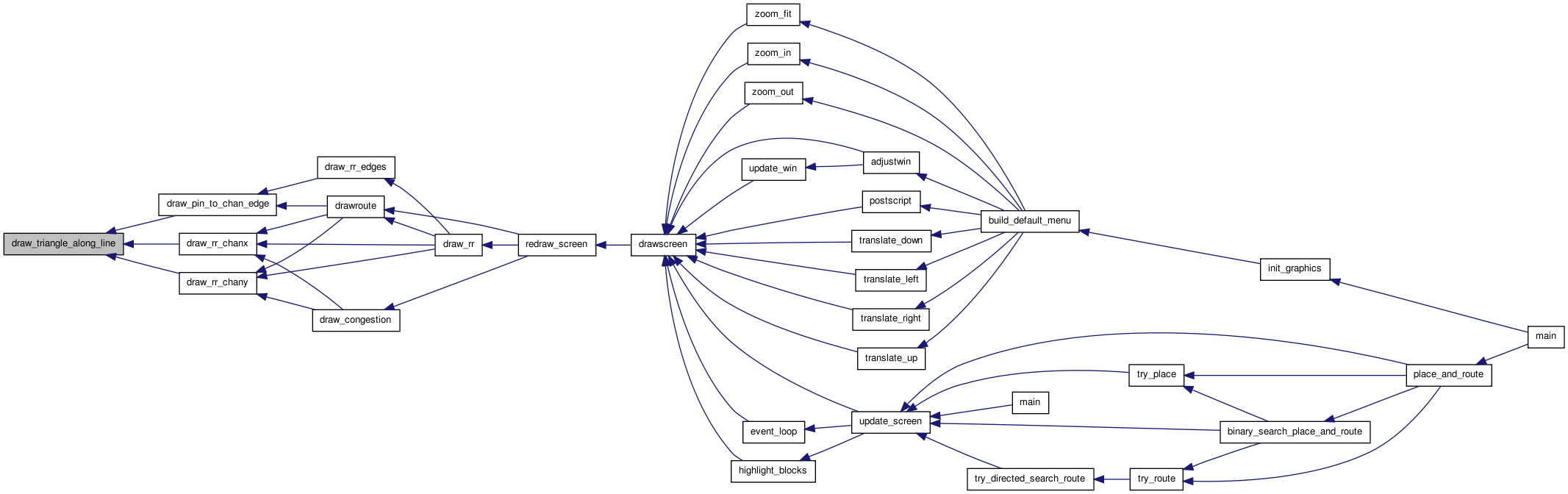
| static void | draw_triangle_along_line (float xend, float yend, float x1, float x2, float y1, float y2) |
| void | set_graphics_state (boolean show_graphics_val, int gr_automode_val, enum e_route_type route_type) |
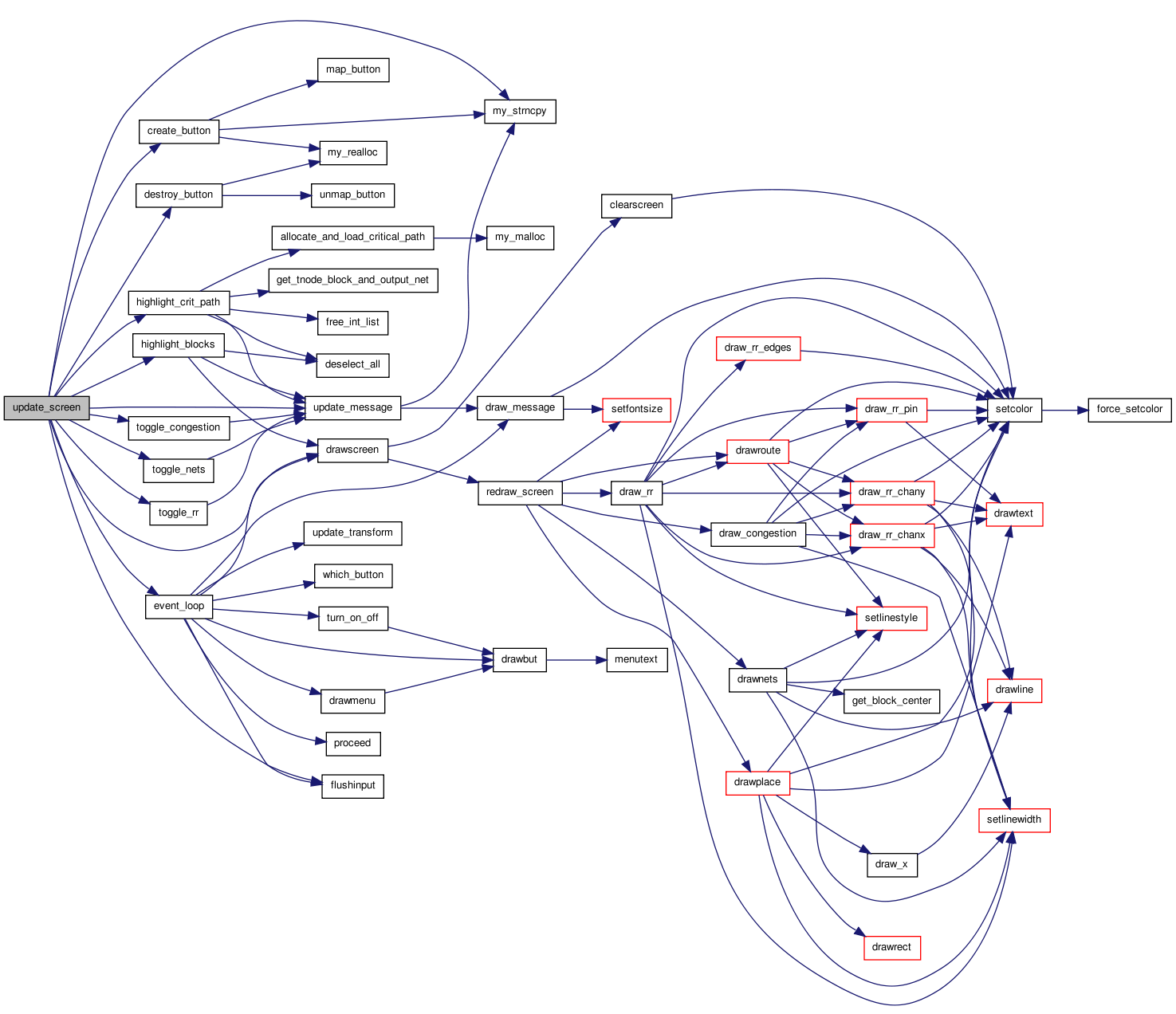
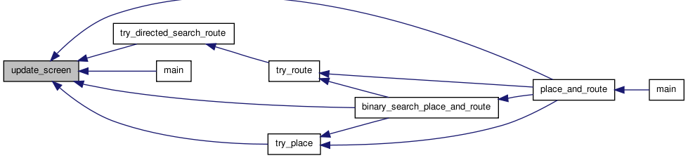
| void | update_screen (int priority, char *msg, enum pic_type pic_on_screen_val, boolean crit_path_button_enabled) |
| void | alloc_draw_structs (void) |
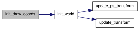
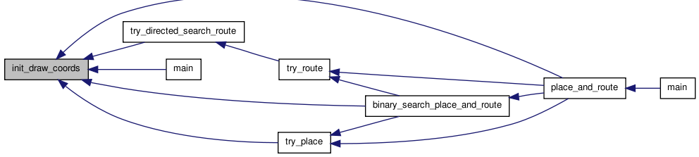
| void | init_draw_coords (float width_val) |
Variables | |
| static boolean | show_nets = FALSE |
| static enum e_draw_rr_toggle | draw_rr_toggle = DRAW_NO_RR |
| static enum e_route_type | draw_route_type |
| static boolean | show_congestion = FALSE |
| static boolean | show_graphics |
| static char | default_message [BUFSIZE] |
| static int | gr_automode |
| static enum pic_type | pic_on_screen = NO_PICTURE |
| static float * | tile_x |
| static float * | tile_y |
| static float | tile_width |
| static float | pin_size |
Define Documentation
Enumeration Type Documentation
| enum e_draw_net_type |
Definition at line 26 of file draw.c.
00027 { ALL_NETS, HIGHLIGHTED };
| enum e_draw_rr_toggle |
- Enumerator:
DRAW_NO_RR DRAW_ALL_RR DRAW_ALL_BUT_BUFFERS_RR DRAW_NODES_AND_SBOX_RR DRAW_NODES_RR DRAW_RR_TOGGLE_MAX
Definition at line 16 of file draw.c.
00017 {
00018     DRAW_NO_RR = 0,
00019     DRAW_ALL_RR,
00020     DRAW_ALL_BUT_BUFFERS_RR,
00021     DRAW_NODES_AND_SBOX_RR,
00022     DRAW_NODES_RR,
00023     DRAW_RR_TOGGLE_MAX
00024 };
| enum e_edge_dir |
Definition at line 29 of file draw.c.
00030 { FROM_X_TO_Y, FROM_Y_TO_X }; /* Chanx to chany or vice versa? */
Function Documentation
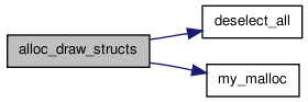
| void alloc_draw_structs | ( | void | ) |
Definition at line 455 of file draw.c.
00456 {
00457
00458     /* Allocate the structures needed to draw the placement and routing.  Set *
00459      * up the default colors for blocks and nets.                             */
00460
00461     tile_x = (float *)my_malloc((nx + 2) * sizeof(float));
00462     tile_y = (float *)my_malloc((ny + 2) * sizeof(float));
00463
00464     net_color = (enum color_types *)
00465         my_malloc(num_nets * sizeof(enum color_types));
00466
00467     block_color = (enum color_types *)
00468         my_malloc(num_blocks * sizeof(enum color_types));
00469
00470     deselect_all();             /* Set initial colors */
00471 }

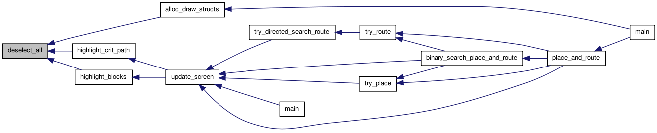
| static void deselect_all | ( | void | ) | [static] |
Definition at line 1940 of file draw.c.
01941 {
01942     /* Sets the color of all clbs and nets to the default.  */
01943
01944     int i;
01945
01946     /* Create some colour highlighting */
01947     for(i = 0; i < num_blocks; i++) {
01948                 if(block[i].type->index < 3) {
01949                         block_color[i] = LIGHTGREY;
01950                 } else if(block[i].type->index < 3 + MAX_BLOCK_COLOURS) {
01951                         block_color[i] = BISQUE + MAX_BLOCK_COLOURS + block[i].type->index - 3;
01952                 } else {
01953                         block_color[i] = BISQUE + 2 * MAX_BLOCK_COLOURS - 1;
01954                 }
01955         }
01956
01957     for(i = 0; i < num_nets; i++)
01958                 net_color[i] = BLACK;
01959 }
| static void draw_chanx_to_chanx_edge | ( | int | from_node, | |
| int | from_track, | |||
| int | to_node, | |||
| int | to_track, | |||
| short | switch_type | |||
| ) | [static] |
Definition at line 1208 of file draw.c.
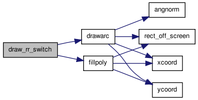
01213 {
01214
01215 /* Draws a connection between two x-channel segments.  Passing in the track *
01216  * numbers allows this routine to be used for both rr_graph and routing     *
01217  * drawing.                                                                 */
01218
01219     float x1, x2, y1, y2;
01220     int from_y, to_y, from_xlow, to_xlow, from_xhigh, to_xhigh;
01221
01222     from_y = rr_node[from_node].ylow;
01223     from_xlow = rr_node[from_node].xlow;
01224     from_xhigh = rr_node[from_node].xhigh;
01225     to_y = rr_node[to_node].ylow;
01226     to_xlow = rr_node[to_node].xlow;
01227     to_xhigh = rr_node[to_node].xhigh;
01228
01229 /* (x1, y1) point on from_node, (x2, y2) point on to_node. */
01230
01231     y1 = tile_y[from_y] + tile_width + 1 + from_track;
01232     y2 = tile_y[to_y] + tile_width + 1 + to_track;
01233
01234
01235     if(to_xhigh < from_xlow)
01236         {                       /* From right to left */
01237             /* UDSD Note by WMF: could never happen for INC wires, unless U-turn. For DEC
01238              * wires this handles well */
01239             x1 = tile_x[from_xlow];
01240             x2 = tile_x[to_xhigh] + tile_width;
01241         }
01242     else if(to_xlow > from_xhigh)
01243         {                       /* From left to right */
01244             /* UDSD Note by WMF: could never happen for DEC wires, unless U-turn. For INC
01245              * wires this handles well */
01246             x1 = tile_x[from_xhigh] + tile_width;
01247             x2 = tile_x[to_xlow];
01248         }
01249
01250 /* Segments overlap in the channel.  Figure out best way to draw.  Have to  *
01251  * make sure the drawing is symmetric in the from rr and to rr so the edges *
01252  * will be drawn on top of each other for bidirectional connections.        */
01253
01254     /* UDSD Modification by WMF Begin */
01255     else
01256         {
01257             if(rr_node[to_node].direction != BI_DIRECTION)
01258                 {
01259                     /* must connect to to_node's wire beginning at x2 */
01260                     if(to_track % 2 == 0)
01261                         {       /* INC wire starts at leftmost edge */
01262                             assert(from_xlow < to_xlow);
01263                             x2 = tile_x[to_xlow];
01264                             /* since no U-turns from_track must be INC as well */
01265                             x1 = tile_x[to_xlow - 1] + tile_width;
01266                         }
01267                     else
01268                         {       /* DEC wire starts at rightmost edge */
01269                             assert(from_xhigh > to_xhigh);
01270                             x2 = tile_x[to_xhigh] + tile_width;
01271                             x1 = tile_x[to_xhigh + 1];
01272                         }
01273                 }
01274             else
01275                 {
01276                     if(to_xlow < from_xlow)
01277                         {       /* Draw from left edge of one to other */
01278                             x1 = tile_x[from_xlow];
01279                             x2 = tile_x[from_xlow - 1] + tile_width;
01280                         }
01281                     else if(from_xlow < to_xlow)
01282                         {
01283                             x1 = tile_x[to_xlow - 1] + tile_width;
01284                             x2 = tile_x[to_xlow];
01285                         }       /* The following then is executed when from_xlow == to_xlow */
01286                     else if(to_xhigh > from_xhigh)
01287                         {       /* Draw from right edge of one to other */
01288                             x1 = tile_x[from_xhigh] + tile_width;
01289                             x2 = tile_x[from_xhigh + 1];
01290                         }
01291                     else if(from_xhigh > to_xhigh)
01292                         {
01293                             x1 = tile_x[to_xhigh + 1];
01294                             x2 = tile_x[to_xhigh] + tile_width;
01295                         }
01296                     else
01297                         {       /* Complete overlap: start and end both align. Draw outside the sbox */
01298                             x1 = tile_x[from_xlow];
01299                             x2 = tile_x[from_xlow] + tile_width;
01300                         }
01301                 }
01302         }
01303     /* UDSD Modification by WMF End */
01304     drawline(x1, y1, x2, y2);
01305
01306     if(draw_rr_toggle == DRAW_ALL_RR)
01307         draw_rr_switch(x1, y1, x2, y2, switch_inf[switch_type].buffered);
01308 }

| static void draw_chanx_to_chany_edge | ( | int | chanx_node, | |
| int | chanx_track, | |||
| int | chany_node, | |||
| int | chany_track, | |||
| enum e_edge_dir | edge_dir, | |||
| short | switch_type | |||
| ) | [static] |
Definition at line 1129 of file draw.c.
01135 {
01136
01137     /* Draws an edge (SBOX connection) between an x-directed channel and a    *
01138      * y-directed channel.                                                    */
01139
01140     float x1, y1, x2, y2;
01141     int chanx_y, chany_x, chanx_xlow, chany_ylow;
01142
01143     chanx_y = rr_node[chanx_node].ylow;
01144     chanx_xlow = rr_node[chanx_node].xlow;
01145     chany_x = rr_node[chany_node].xlow;
01146     chany_ylow = rr_node[chany_node].ylow;
01147
01148     /* (x1,y1): point on CHANX segment, (x2,y2): point on CHANY segment. */
01149
01150     y1 = tile_y[chanx_y] + tile_width + 1. + chanx_track;
01151     x2 = tile_x[chany_x] + tile_width + 1. + chany_track;
01152
01153     if(chanx_xlow <= chany_x)
01154         {                       /* Can draw connection going right */
01155             x1 = tile_x[chany_x] + tile_width;
01156             /* UDSD by AY Start */
01157             if(rr_node[chanx_node].direction != BI_DIRECTION)
01158                 {
01159                     if(edge_dir == FROM_X_TO_Y)
01160                         {
01161                             if((chanx_track % 2) == 1)
01162                                 {       /* UDSD Modifications by WMF: If dec wire, then going left */
01163                                     x1 = tile_x[chany_x + 1];
01164                                 }
01165                         }
01166                 }
01167             /* UDSD by AY End */
01168         }
01169     else
01170         {                       /* Must draw connection going left. */
01171             x1 = tile_x[chanx_xlow];
01172         }
01173
01174     if(chany_ylow <= chanx_y)
01175         {                       /* Can draw connection going up. */
01176             y2 = tile_y[chanx_y] + tile_width;
01177             /* UDSD by AY Start */
01178             if(rr_node[chany_node].direction != BI_DIRECTION)
01179                 {
01180                     if(edge_dir == FROM_Y_TO_X)
01181                         {
01182                             if((chany_track % 2) == 1)
01183                                 {       /* UDSD Modifications by WMF: If dec wire, then going down */
01184                                     y2 = tile_y[chanx_y + 1];
01185                                 }
01186                         }
01187                 }
01188             /* UDSD by AY End */
01189         }
01190     else
01191         {                       /* Must draw connection going down. */
01192             y2 = tile_y[chany_ylow];
01193         }
01194
01195     drawline(x1, y1, x2, y2);
01196
01197     if(draw_rr_toggle != DRAW_ALL_RR)
01198         return;
01199
01200     if(edge_dir == FROM_X_TO_Y)
01201         draw_rr_switch(x1, y1, x2, y2, switch_inf[switch_type].buffered);
01202     else
01203         draw_rr_switch(x2, y2, x1, y1, switch_inf[switch_type].buffered);
01204 }

| static void draw_chany_to_chany_edge | ( | int | from_node, | |
| int | from_track, | |||
| int | to_node, | |||
| int | to_track, | |||
| short | switch_type | |||
| ) | [static] |
Definition at line 1312 of file draw.c.
01317 {
01318
01319 /* Draws a connection between two y-channel segments.  Passing in the track *
01320  * numbers allows this routine to be used for both rr_graph and routing     *
01321  * drawing.                                                                 */
01322
01323     float x1, x2, y1, y2;
01324     int from_x, to_x, from_ylow, to_ylow, from_yhigh, to_yhigh;
01325
01326     from_x = rr_node[from_node].xlow;
01327     from_ylow = rr_node[from_node].ylow;
01328     from_yhigh = rr_node[from_node].yhigh;
01329     to_x = rr_node[to_node].xlow;
01330     to_ylow = rr_node[to_node].ylow;
01331     to_yhigh = rr_node[to_node].yhigh;
01332
01333 /* (x1, y1) point on from_node, (x2, y2) point on to_node. */
01334
01335     x1 = tile_x[from_x] + tile_width + 1 + from_track;
01336     x2 = tile_x[to_x] + tile_width + 1 + to_track;
01337
01338     if(to_yhigh < from_ylow)
01339         {                       /* From upper to lower */
01340             y1 = tile_y[from_ylow];
01341             y2 = tile_y[to_yhigh] + tile_width;
01342         }
01343     else if(to_ylow > from_yhigh)
01344         {                       /* From lower to upper */
01345             y1 = tile_y[from_yhigh] + tile_width;
01346             y2 = tile_y[to_ylow];
01347         }
01348
01349 /* Segments overlap in the channel.  Figure out best way to draw.  Have to  *
01350  * make sure the drawing is symmetric in the from rr and to rr so the edges *
01351  * will be drawn on top of each other for bidirectional connections.        */
01352
01353     /* UDSD Modification by WMF Begin */
01354     else
01355         {
01356             if(rr_node[to_node].direction != BI_DIRECTION)
01357                 {
01358                     if(to_track % 2 == 0)
01359                         {       /* INC wire starts at bottom edge */
01360                             assert(from_ylow < to_ylow);
01361                             y2 = tile_y[to_ylow];
01362                             /* since no U-turns from_track must be INC as well */
01363                             y1 = tile_y[to_ylow - 1] + tile_width;
01364                         }
01365                     else
01366                         {       /* DEC wire starts at top edge */
01367                             if(!(from_yhigh > to_yhigh))
01368                                 {
01369                                     printf
01370                                         ("from_yhigh (%d) !> to_yhigh (%d).\n",
01371                                          from_yhigh, to_yhigh);
01372                                     printf
01373                                         ("from is (%d, %d) to (%d, %d) track %d.\n",
01374                                          rr_node[from_node].xhigh,
01375                                          rr_node[from_node].yhigh,
01376                                          rr_node[from_node].xlow,
01377                                          rr_node[from_node].ylow,
01378                                          rr_node[from_node].ptc_num);
01379                                     printf
01380                                         ("to is (%d, %d) to (%d, %d) track %d.\n",
01381                                          rr_node[to_node].xhigh,
01382                                          rr_node[to_node].yhigh,
01383                                          rr_node[to_node].xlow,
01384                                          rr_node[to_node].ylow,
01385                                          rr_node[to_node].ptc_num);
01386                                     exit(1);
01387                                 }
01388                             y2 = tile_y[to_yhigh] + tile_width;
01389                             y1 = tile_y[to_yhigh + 1];
01390                         }
01391                 }
01392             else
01393                 {
01394                     if(to_ylow < from_ylow)
01395                         {       /* Draw from bottom edge of one to other. */
01396                             y1 = tile_y[from_ylow];
01397                             y2 = tile_y[from_ylow - 1] + tile_width;
01398                         }
01399                     else if(from_ylow < to_ylow)
01400                         {
01401                             y1 = tile_y[to_ylow - 1] + tile_width;
01402                             y2 = tile_y[to_ylow];
01403                         }
01404                     else if(to_yhigh > from_yhigh)
01405                         {       /* Draw from top edge of one to other. */
01406                             y1 = tile_y[from_yhigh] + tile_width;
01407                             y2 = tile_y[from_yhigh + 1];
01408                         }
01409                     else if(from_yhigh > to_yhigh)
01410                         {
01411                             y1 = tile_y[to_yhigh + 1];
01412                             y2 = tile_y[to_yhigh] + tile_width;
01413                         }
01414                     else
01415                         {       /* Complete overlap: start and end both align. Draw outside the sbox */
01416                             y1 = tile_y[from_ylow];
01417                             y2 = tile_y[from_ylow] + tile_width;
01418                         }
01419                 }
01420         }
01421     /* UDSD Modification by WMF End */
01422     drawline(x1, y1, x2, y2);
01423
01424     if(draw_rr_toggle == DRAW_ALL_RR)
01425         draw_rr_switch(x1, y1, x2, y2, switch_inf[switch_type].buffered);
01426 }


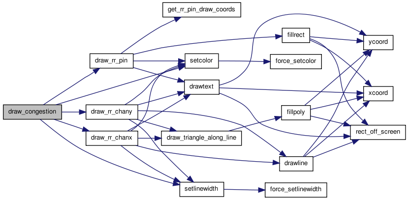
| static void draw_congestion | ( | void | ) | [static] |
Definition at line 715 of file draw.c.
00716 {
00717
00718     /* Draws all the overused routing resources (i.e. congestion) in RED.   */
00719
00720     int inode, itrack;
00721
00722     setcolor(RED);
00723     setlinewidth(2);
00724
00725     for(inode = 0; inode < num_rr_nodes; inode++)
00726         {
00727             if(rr_node[inode].occ > rr_node[inode].capacity)
00728                 {
00729                     switch (rr_node[inode].type)
00730                         {
00731                         case CHANX:
00732                             itrack = rr_node[inode].ptc_num;
00733                             draw_rr_chanx(inode, itrack);
00734                             break;
00735
00736                         case CHANY:
00737                             itrack = rr_node[inode].ptc_num;
00738                             draw_rr_chany(inode, itrack);
00739                             break;
00740
00741                         case IPIN:
00742                         case OPIN:
00743                             draw_rr_pin(inode, RED);
00744                             break;
00745                         }
00746                 }
00747         }
00748 }
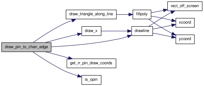
| static void draw_pin_to_chan_edge | ( | int | pin_node, | |
| int | chan_node | |||
| ) | [static] |
Definition at line 1998 of file draw.c.
02000 {
02001
02002 /* This routine draws an edge from the pin_node to the chan_node (CHANX or   *
02003  * CHANY).  The connection is made to the nearest end of the track instead   *
02004  * of perpundicular to the track to symbolize a single-drive connection.     *
02005  * If mark_conn is TRUE, draw a box where the pin connects to the track      *
02006  * (useful for drawing  the rr graph)                                        */
02007
02008 /* TODO: Fix this for global routing, currently for detailed only */
02009
02010     t_rr_type chan_type;
02011     int grid_x, grid_y, pin_num, chan_xlow, chan_ylow, ioff, height;
02012     float x1, x2, y1, y2;
02013     int start, end, i;
02014     int itrack;
02015     float xend, yend;
02016     float draw_pin_off;
02017     enum e_direction direction;
02018     enum e_side iside;
02019     t_type_ptr type;
02020
02021     direction = rr_node[chan_node].direction;
02022     grid_x = rr_node[pin_node].xlow;
02023     grid_y = rr_node[pin_node].ylow;
02024     pin_num = rr_node[pin_node].ptc_num;
02025     chan_type = rr_node[chan_node].type;
02026     itrack = rr_node[chan_node].ptc_num;
02027     type = grid[grid_x][grid_y].type;
02028
02029     ioff = grid[grid_x][grid_y].offset;
02030     /* large block begins at primary tile (offset == 0) */
02031     grid_y = grid_y - ioff;
02032     height = grid[grid_x][grid_y].type->height;
02033     chan_ylow = rr_node[chan_node].ylow;
02034     chan_xlow = rr_node[chan_node].xlow;
02035     start = -1;
02036     end = -1;
02037
02038
02039     switch (chan_type)
02040         {
02041
02042         case CHANX:
02043             start = rr_node[chan_node].xlow;
02044             end = rr_node[chan_node].xhigh;
02045             if(is_opin(pin_num, type))
02046                 {
02047                     if(direction == INC_DIRECTION)
02048                         {
02049                             end = rr_node[chan_node].xlow;
02050                         }
02051                     else if(direction == DEC_DIRECTION)
02052                         {
02053                             start = rr_node[chan_node].xhigh;
02054                         }
02055                 }
02056
02057             start = max(start, grid_x);
02058             end = min(end, grid_x);     /* Width is 1 always */
02059             assert(end >= start);       /* Make sure we are nearby */
02060
02061             if((grid_y + height - 1) == chan_ylow)
02062                 {
02063                     iside = TOP;
02064                     ioff = height - 1;
02065                     draw_pin_off = pin_size;
02066                 }
02067             else
02068                 {
02069                     assert((grid_y - 1) == chan_ylow);
02070
02071                     iside = BOTTOM;
02072                     ioff = 0;
02073                     draw_pin_off = -pin_size;
02074                 }
02075             assert(grid[grid_x][grid_y].type->pinloc[ioff][iside][pin_num]);
02076
02077             get_rr_pin_draw_coords(pin_node, iside, ioff, &x1, &y1);
02078             y1 += draw_pin_off;
02079
02080             y2 = tile_y[rr_node[chan_node].ylow] + tile_width + 1. + itrack;
02081             x2 = x1;
02082             if(is_opin(pin_num, type))
02083                 {
02084                     if(direction == INC_DIRECTION)
02085                         {
02086                             x2 = tile_x[rr_node[chan_node].xlow];
02087                         }
02088                     else if(direction == DEC_DIRECTION)
02089                         {
02090                             x2 = tile_x[rr_node[chan_node].xhigh] +
02091                                 tile_width;
02092                         }
02093                 }
02094             break;
02095
02096         case CHANY:
02097             start = rr_node[chan_node].ylow;
02098             end = rr_node[chan_node].yhigh;
02099             if(is_opin(pin_num, type))
02100                 {
02101                     if(direction == INC_DIRECTION)
02102                         {
02103                             end = rr_node[chan_node].ylow;
02104                         }
02105                     else if(direction == DEC_DIRECTION)
02106                         {
02107                             start = rr_node[chan_node].yhigh;
02108                         }
02109                 }
02110
02111             start = max(start, grid_y);
02112             end = min(end, (grid_y + height - 1));      /* Width is 1 always */
02113             assert(end >= start);       /* Make sure we are nearby */
02114
02115             if((grid_x) == chan_xlow)
02116                 {
02117                     iside = RIGHT;
02118                     draw_pin_off = pin_size;
02119                 }
02120             else
02121                 {
02122                     assert((grid_x - 1) == chan_xlow);
02123                     iside = LEFT;
02124                     draw_pin_off = -pin_size;
02125                 }
02126             for(i = start; i <= end; i++)
02127                 {
02128                     ioff = i - grid_y;
02129                     assert(ioff >= 0 && ioff < type->height);
02130                     /* Once we find the location, break out, this will leave ioff pointing
02131                      * to the correct offset.  If an offset is not found, the assertion after
02132                      * this will fail.  With the correct routing graph, the assertion will not
02133                      * be triggered.  This also takes care of connecting a wire once to multiple
02134                      * physical pins on the same side. */
02135                     if(grid[grid_x][grid_y].type->
02136                        pinloc[ioff][iside][pin_num])
02137                         {
02138                             break;
02139                         }
02140                 }
02141             assert(grid[grid_x][grid_y].type->pinloc[ioff][iside][pin_num]);
02142
02143             get_rr_pin_draw_coords(pin_node, iside, ioff, &x1, &y1);
02144             x1 += draw_pin_off;
02145
02146             x2 = tile_x[chan_xlow] + tile_width + 1 + itrack;
02147             y2 = y1;
02148             if(is_opin(pin_num, type))
02149                 {
02150                     if(direction == INC_DIRECTION)
02151                         {
02152                             y2 = tile_y[rr_node[chan_node].ylow];
02153                         }
02154                     else if(direction == DEC_DIRECTION)
02155                         {
02156                             y2 = tile_y[rr_node[chan_node].yhigh] +
02157                                 tile_width;
02158                         }
02159                 }
02160             break;
02161
02162         default:
02163             printf
02164                 ("Error in draw_pin_to_chan_edge:  invalid channel node %d.\n",
02165                  chan_node);
02166             exit(1);
02167         }
02168
02169     drawline(x1, y1, x2, y2);
02170     if(direction == BI_DIRECTION || !is_opin(pin_num, type))
02171         {
02172             draw_x(x2, y2, 0.7 * pin_size);
02173         }
02174     else
02175         {
02176             xend = x2 + (x1 - x2) / 10.;
02177             yend = y2 + (y1 - y2) / 10.;
02178             draw_triangle_along_line(xend, yend, x1, x2, y1, y2);
02179         }
02180 }
| void draw_rr | ( | void | ) | [static] |
Definition at line 752 of file draw.c.
00753 {
00754
00755     /* Draws the routing resources that exist in the FPGA, if the user wants *
00756      * them drawn.                                                           */
00757
00758     int inode, itrack;
00759
00760     if(draw_rr_toggle == DRAW_NO_RR)
00761         {
00762             setlinewidth(3);
00763             drawroute(HIGHLIGHTED);
00764             setlinewidth(0);
00765             return;
00766         }
00767
00768     setlinestyle(SOLID);
00769     setlinewidth(0);
00770
00771     for(inode = 0; inode < num_rr_nodes; inode++)
00772         {
00773             switch (rr_node[inode].type)
00774                 {
00775
00776                 case SOURCE:
00777                 case SINK:
00778                     break;      /* Don't draw. */
00779
00780                 case CHANX:
00781                     setcolor(BLACK);
00782                     itrack = rr_node[inode].ptc_num;
00783                     draw_rr_chanx(inode, itrack);
00784                     draw_rr_edges(inode);
00785                     break;
00786
00787                 case CHANY:
00788                     setcolor(BLACK);
00789                     itrack = rr_node[inode].ptc_num;
00790                     draw_rr_chany(inode, itrack);
00791                     draw_rr_edges(inode);
00792                     break;
00793
00794                 case IPIN:
00795                     draw_rr_pin(inode, BLUE);
00796                     break;
00797
00798                 case OPIN:
00799                     draw_rr_pin(inode, RED);
00800                     setcolor(RED);
00801                     draw_rr_edges(inode);
00802                     break;
00803
00804                 default:
00805                     printf
00806                         ("Error in draw_rr:  Unexpected rr_node type: %d.\n",
00807                          rr_node[inode].type);
00808                     exit(1);
00809                 }
00810         }
00811
00812     setlinewidth(3);
00813     drawroute(HIGHLIGHTED);
00814     setlinewidth(0);
00815 }
| static void draw_rr_chanx | ( | int | inode, | |
| int | itrack | |||
| ) | [static] |
Definition at line 819 of file draw.c.
00821 {
00822
00823     /* Draws an x-directed channel segment.                       */
00824
00825     enum
00826     { BUFFSIZE = 80 };
00827     float x1, x2, y;
00828     float y1, y2;               /* UDSD by AY */
00829     int k;                      /* UDSD by AY */
00830     char str[BUFFSIZE];
00831
00832     /* Track 0 at bottom edge, closest to "owning" clb. */
00833
00834     x1 = tile_x[rr_node[inode].xlow];
00835     x2 = tile_y[rr_node[inode].xhigh] + tile_width;
00836     y = tile_y[rr_node[inode].ylow] + tile_width + 1.0 + itrack;
00837     drawline(x1, y, x2, y);
00838
00839     /* UDSD by AY Start */
00840     y1 = y - 0.25;
00841     y2 = y + 0.25;
00842
00843     if(rr_node[inode].direction == INC_DIRECTION)
00844         {
00845             setlinewidth(2);
00846             setcolor(YELLOW);
00847             drawline(x1, y1, x1, y2);   /* Draw a line at start of wire to indicate mux */
00848
00849             /* Mux balence numbers */
00850             setcolor(BLACK);
00851             sprintf(str, "%d", rr_node[inode].fan_in);
00852             drawtext(x1, y, str, 5);
00853
00854             setcolor(BLACK);
00855             setlinewidth(0);
00856             draw_triangle_along_line(x2 - 0.15, y, x1, x2, y, y);
00857
00858             setcolor(LIGHTGREY);
00859             /* TODO: this looks odd, why does it ignore final block? does this mean nothing appears with L=1 ? */
00860             for(k = rr_node[inode].xlow; k < rr_node[inode].xhigh; k++)
00861                 {
00862                     x2 = tile_x[k] + tile_width;
00863                     draw_triangle_along_line(x2 - 0.15, y, x1, x2, y, y);
00864                     x2 = tile_x[k + 1];
00865                     draw_triangle_along_line(x2 + 0.15, y, x1, x2, y, y);
00866                 }
00867             setcolor(BLACK);
00868         }
00869     else if(rr_node[inode].direction == DEC_DIRECTION)
00870         {
00871             setlinewidth(2);
00872             setcolor(YELLOW);
00873             drawline(x2, y1, x2, y2);
00874
00875             /* Mux balance numbers */
00876             setcolor(BLACK);
00877             sprintf(str, "%d", rr_node[inode].fan_in);
00878             drawtext(x2, y, str, 5);
00879
00880             setlinewidth(0);
00881             draw_triangle_along_line(x1 + 0.15, y, x2, x1, y, y);
00882             setcolor(LIGHTGREY);
00883             for(k = rr_node[inode].xhigh; k > rr_node[inode].xlow; k--)
00884                 {
00885                     x1 = tile_x[k];
00886                     draw_triangle_along_line(x1 + 0.15, y, x2, x1, y, y);
00887                     x1 = tile_x[k - 1] + tile_width;
00888                     draw_triangle_along_line(x1 - 0.15, y, x2, x1, y, y);
00889                 }
00890             setcolor(BLACK);
00891         }
00892     /* UDSD by AY End */
00893 }
| static void draw_rr_chany | ( | int | inode, | |
| int | itrack | |||
| ) | [static] |
Definition at line 897 of file draw.c.
00899 {
00900
00901     /* Draws a y-directed channel segment.                       */
00902     enum
00903     { BUFFSIZE = 80 };
00904     float x, y1, y2;
00905     float x1, x2;               /* UDSD by AY */
00906     int k;                      /* UDSD by AY */
00907     char str[BUFFSIZE];
00908
00909     /* Track 0 at left edge, closest to "owning" clb. */
00910
00911     x = tile_x[rr_node[inode].xlow] + tile_width + 1. + itrack;
00912     y1 = tile_y[rr_node[inode].ylow];
00913     y2 = tile_y[rr_node[inode].yhigh] + tile_width;
00914     drawline(x, y1, x, y2);
00915
00916     /* UDSD by AY Start */
00917     x1 = x - 0.25;
00918     x2 = x + 0.25;
00919     if(rr_node[inode].direction == INC_DIRECTION)
00920         {
00921             setlinewidth(2);
00922             setcolor(YELLOW);
00923             drawline(x1, y1, x2, y1);
00924
00925             /* UDSD Modifications by WMF Begin */
00926             setcolor(BLACK);
00927             sprintf(str, "%d", rr_node[inode].fan_in);
00928             drawtext(x, y1, str, 5);
00929             setcolor(BLACK);
00930             /* UDSD Modifications by WMF End */
00931
00932             setlinewidth(0);
00933             draw_triangle_along_line(x, y2 - 0.15, x, x, y1, y2);
00934             setcolor(LIGHTGREY);
00935             for(k = rr_node[inode].ylow; k < rr_node[inode].yhigh; k++)
00936                 {
00937                     y2 = tile_y[k] + tile_width;
00938                     draw_triangle_along_line(x, y2 - 0.15, x, x, y1, y2);
00939                     y2 = tile_y[k + 1];
00940                     draw_triangle_along_line(x, y2 + 0.15, x, x, y1, y2);
00941                 }
00942             setcolor(BLACK);
00943         }
00944     else if(rr_node[inode].direction == DEC_DIRECTION)
00945         {
00946             setlinewidth(2);
00947             setcolor(YELLOW);
00948             drawline(x1, y2, x2, y2);
00949
00950             /* UDSD Modifications by WMF Begin */
00951             setcolor(BLACK);
00952             sprintf(str, "%d", rr_node[inode].fan_in);
00953             drawtext(x, y2, str, 5);
00954             setcolor(BLACK);
00955             /* UDSD Modifications by WMF End */
00956
00957             setlinewidth(0);
00958             draw_triangle_along_line(x, y1 + 0.15, x, x, y2, y1);
00959             setcolor(LIGHTGREY);
00960             for(k = rr_node[inode].yhigh; k > rr_node[inode].ylow; k--)
00961                 {
00962                     y1 = tile_y[k];
00963                     draw_triangle_along_line(x, y1 + 0.15, x, x, y2, y1);
00964                     y1 = tile_y[k - 1] + tile_width;
00965                     draw_triangle_along_line(x, y1 - 0.15, x, x, y2, y1);
00966                 }
00967             setcolor(BLACK);
00968         }
00969     /* UDSD by AY End */
00970 }


| static void draw_rr_edges | ( | int | from_node | ) | [static] |
Definition at line 974 of file draw.c.
00975 {
00976
00977     /* Draws all the edges that the user wants shown between inode and what it *
00978      * connects to.  inode is assumed to be a CHANX, CHANY, or OPIN.           */
00979
00980     t_rr_type from_type, to_type;
00981     int iedge, to_node, from_ptc_num, to_ptc_num;
00982     short switch_type;
00983
00984     from_type = rr_node[inode].type;
00985
00986     if((draw_rr_toggle == DRAW_NODES_RR) ||
00987        (draw_rr_toggle == DRAW_NODES_AND_SBOX_RR && from_type == OPIN))
00988         {
00989             return;             /* Nothing to draw. */
00990         }
00991
00992     from_ptc_num = rr_node[inode].ptc_num;
00993
00994     for(iedge = 0; iedge < rr_node[inode].num_edges; iedge++)
00995         {
00996             to_node = rr_node[inode].edges[iedge];
00997             to_type = rr_node[to_node].type;
00998             to_ptc_num = rr_node[to_node].ptc_num;
00999
01000             switch (from_type)
01001                 {
01002
01003                 case OPIN:
01004                     switch (to_type)
01005                         {
01006                         case CHANX:
01007                         case CHANY:
01008                             setcolor(RED);
01009                             draw_pin_to_chan_edge(inode, to_node);
01010                             break;
01011
01012                         default:
01013                             printf
01014                                 ("Error in draw_rr_edges:  node %d (type: %d) connects to \n"
01015                                  "node %d (type: %d).\n", inode, from_type,
01016                                  to_node, to_type);
01017                             exit(1);
01018                             break;
01019                         }
01020                     break;
01021
01022                 case CHANX:     /* from_type */
01023                     switch (to_type)
01024                         {
01025                         case IPIN:
01026                             if(draw_rr_toggle == DRAW_NODES_AND_SBOX_RR)
01027                                 {
01028                                     break;
01029                                 }
01030
01031                             setcolor(BLUE);
01032                             draw_pin_to_chan_edge(to_node, inode);
01033                             break;
01034
01035                         case CHANX:
01036                             setcolor(DARKGREEN);
01037                             switch_type = rr_node[inode].switches[iedge];
01038                             draw_chanx_to_chanx_edge(inode, from_ptc_num,
01039                                                      to_node, to_ptc_num,
01040                                                      switch_type);
01041                             break;
01042
01043                         case CHANY:
01044                             setcolor(DARKGREEN);
01045                             switch_type = rr_node[inode].switches[iedge];
01046                             draw_chanx_to_chany_edge(inode, from_ptc_num,
01047                                                      to_node, to_ptc_num,
01048                                                      FROM_X_TO_Y,
01049                                                      switch_type);
01050                             break;
01051
01052                         default:
01053                             printf
01054                                 ("Error in draw_rr_edges:  node %d (type: %d) connects to \n"
01055                                  "node %d (type: %d).\n", inode, from_type,
01056                                  to_node, to_type);
01057                             exit(1);
01058                             break;
01059                         }
01060                     break;
01061
01062
01063                 case CHANY:     /* from_type */
01064                     switch (to_type)
01065                         {
01066                         case IPIN:
01067                             if(draw_rr_toggle == DRAW_NODES_AND_SBOX_RR)
01068                                 {
01069                                     break;
01070                                 }
01071
01072                             setcolor(BLUE);
01073                             draw_pin_to_chan_edge(to_node, inode);
01074                             break;
01075
01076                         case CHANX:
01077                             setcolor(DARKGREEN);
01078                             switch_type = rr_node[inode].switches[iedge];
01079                             draw_chanx_to_chany_edge(to_node, to_ptc_num,
01080                                                      inode, from_ptc_num,
01081                                                      FROM_Y_TO_X,
01082                                                      switch_type);
01083                             break;
01084
01085                         case CHANY:
01086                             setcolor(DARKGREEN);
01087                             switch_type = rr_node[inode].switches[iedge];
01088                             draw_chany_to_chany_edge(inode, from_ptc_num,
01089                                                      to_node, to_ptc_num,
01090                                                      switch_type);
01091                             break;
01092
01093                         default:
01094                             printf
01095                                 ("Error in draw_rr_edges:  node %d (type: %d) connects to \n"
01096                                  "node %d (type: %d).\n", inode, from_type,
01097                                  to_node, to_type);
01098                             exit(1);
01099                             break;
01100                         }
01101                     break;
01102
01103                 default:        /* from_type */
01104                     printf
01105                         ("Error:  draw_rr_edges called with node %d of type %d.\n",
01106                          inode, from_type);
01107                     exit(1);
01108                     break;
01109                 }
01110         }                       /* End of for each edge loop */
01111 }
| static void draw_rr_pin | ( | int | inode, | |
| enum color_types | color | |||
| ) | [static] |
Definition at line 1478 of file draw.c.
01480 {
01481
01482     /* Draws an IPIN or OPIN rr_node.  Note that the pin can appear on more    *
01483      * than one side of a clb.  Also note that this routine can change the     *
01484      * current color to BLACK.                                                 */
01485
01486     int ipin, i, j, iside, iclass, ioff;
01487     float xcen, ycen;
01488     char str[BUFSIZE];
01489     t_type_ptr type;
01490
01491     i = rr_node[inode].xlow;
01492     j = rr_node[inode].ylow;
01493     ipin = rr_node[inode].ptc_num;
01494     type = grid[i][j].type;
01495     ioff = grid[i][j].offset;
01496
01497     setcolor(color);
01498     iclass = type->pin_class[ipin];
01499     /* TODO: This is where we can hide fringe physical pins and also identify globals (hide, color, show) */
01500     for(iside = 0; iside < 4; iside++)
01501         {
01502             if(type->pinloc[grid[i][j].offset][iside][ipin])
01503                 {               /* Pin exists on this side. */
01504                     get_rr_pin_draw_coords(inode, iside, ioff, &xcen, &ycen);
01505                     fillrect(xcen - pin_size, ycen - pin_size,
01506                              xcen + pin_size, ycen + pin_size);
01507                     sprintf(str, "%d", ipin);
01508                     setcolor(BLACK);
01509                     drawtext(xcen, ycen, str, 2 * pin_size);
01510                     setcolor(color);
01511                 }
01512         }
01513 }
| static void draw_rr_switch | ( | float | from_x, | |
| float | from_y, | |||
| float | to_x, | |||
| float | to_y, | |||
| boolean | buffered | |||
| ) | [static] |
Definition at line 1430 of file draw.c.
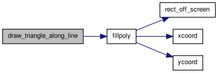
01435 {
01436
01437 /* Draws a buffer (triangle) or pass transistor (circle) on the edge        *
01438  * connecting from to to, depending on the status of buffered.  The drawing *
01439  * is closest to the from_node, since it reflects the switch type of from.  */
01440
01441     const float switch_rad = 0.15;
01442     float magnitude, xcen, ycen, xdelta, ydelta, xbaseline, ybaseline;
01443     float xunit, yunit;
01444     t_point poly[3];
01445
01446     xcen = from_x + (to_x - from_x) / 10.;
01447     ycen = from_y + (to_y - from_y) / 10.;
01448
01449     if(!buffered)
01450         {                       /* Draw a circle for a pass transistor */
01451             drawarc(xcen, ycen, switch_rad, 0., 360.);
01452         }
01453     else
01454         {                       /* Buffer */
01455             xdelta = to_x - from_x;
01456             ydelta = to_y - from_y;
01457             magnitude = sqrt(xdelta * xdelta + ydelta * ydelta);
01458             xunit = xdelta / magnitude;
01459             yunit = ydelta / magnitude;
01460             poly[0].x = xcen + xunit * switch_rad;
01461             poly[0].y = ycen + yunit * switch_rad;
01462             xbaseline = xcen - xunit * switch_rad;
01463             ybaseline = ycen - yunit * switch_rad;
01464
01465 /* Recall: perpendicular vector to the unit vector along the switch (xv, yv) *
01466  * is (yv, -xv).                                                             */
01467
01468             poly[1].x = xbaseline + yunit * switch_rad;
01469             poly[1].y = ybaseline - xunit * switch_rad;
01470             poly[2].x = xbaseline - yunit * switch_rad;
01471             poly[2].y = ybaseline + xunit * switch_rad;
01472             fillpoly(poly, 3);
01473         }
01474 }
| static void draw_triangle_along_line | ( | float | xend, | |
| float | yend, | |||
| float | x1, | |||
| float | x2, | |||
| float | y1, | |||
| float | y2 | |||
| ) | [static] |
Definition at line 1964 of file draw.c.
01970 {
01971     float switch_rad = 0.15;
01972     float xdelta, ydelta;
01973     float magnitude;
01974     float xunit, yunit;
01975     float xbaseline, ybaseline;
01976     t_point poly[3];
01977
01978     xdelta = x2 - x1;
01979     ydelta = y2 - y1;
01980     magnitude = sqrt(xdelta * xdelta + ydelta * ydelta);
01981     xunit = xdelta / magnitude;
01982     yunit = ydelta / magnitude;
01983
01984     poly[0].x = xend + xunit * switch_rad;
01985     poly[0].y = yend + yunit * switch_rad;
01986     xbaseline = xend - xunit * switch_rad;
01987     ybaseline = yend - yunit * switch_rad;
01988     poly[1].x = xbaseline + yunit * switch_rad;
01989     poly[1].y = ybaseline - xunit * switch_rad;
01990     poly[2].x = xbaseline - yunit * switch_rad;
01991     poly[2].y = ybaseline + xunit * switch_rad;
01992
01993     fillpoly(poly, 3);
01994 }
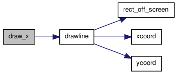
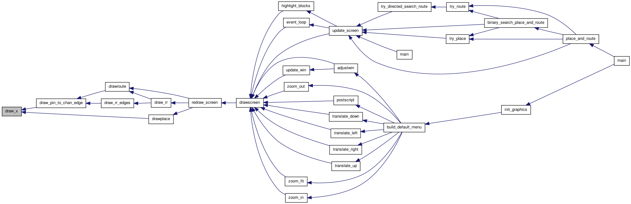
| static void draw_x | ( | float | x, | |
| float | y, | |||
| float | size | |||
| ) | [static] |
Definition at line 1114 of file draw.c.
01117 {
01118
01119     /* Draws an X centered at (x,y).  The width and height of the X are each    *
01120      * 2 * size.                                                                */
01121
01122     drawline(x - size, y + size, x + size, y - size);
01123     drawline(x - size, y - size, x + size, y + size);
01124 }
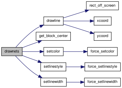
| static void drawnets | ( | void | ) | [static] |
Definition at line 637 of file draw.c.
00638 {
00639
00640     /* This routine draws the nets on the placement.  The nets have not *
00641      * yet been routed, so we just draw a chain showing a possible path *
00642      * for each net.  This gives some idea of future congestion.        */
00643
00644     int inet, ipin, b1, b2;
00645     float x1, y1, x2, y2;
00646
00647     setlinestyle(SOLID);
00648     setlinewidth(0);
00649
00650     /* Draw the net as a star from the source to each sink. Draw from centers of *
00651      * blocks (or sub blocks in the case of IOs).                                */
00652
00653     for(inet = 0; inet < num_nets; inet++)
00654         {
00655             if(net[inet].is_global)
00656                 continue;       /* Don't draw global nets. */
00657
00658             setcolor(net_color[inet]);
00659             b1 = net[inet].node_block[0];       /* The DRIVER */
00660             get_block_center(b1, &x1, &y1);
00661
00662             for(ipin = 1; ipin < (net[inet].num_sinks + 1); ipin++)
00663                 {
00664                     b2 = net[inet].node_block[ipin];
00665                     get_block_center(b2, &x2, &y2);
00666                     drawline(x1, y1, x2, y2);
00667
00668                     /* Uncomment to draw a chain instead of a star. */
00669                     /*      x1 = x2;  */
00670                     /*      y1 = y2;  */
00671                 }
00672         }
00673 }
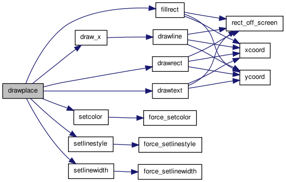
| static void drawplace | ( | void | ) | [static] |
Definition at line 519 of file draw.c.
00520 {
00521
00522     /* Draws the blocks placed on the proper clbs.  Occupied blocks are darker colours *
00523      * while empty ones are lighter colours and have a dashed border.      */
00524
00525     float sub_tile_step;
00526     float x1, y1, x2, y2;
00527     int i, j, k, bnum;
00528     int num_sub_tiles;
00529     int height;
00530
00531     setlinewidth(0);
00532
00533     for(i = 0; i <= (nx + 1); i++)
00534         {
00535             for(j = 0; j <= (ny + 1); j++)
00536                 {
00537                     /* Only the first block of a group should control drawing */
00538                     if(grid[i][j].offset > 0)
00539                         continue;
00540
00541                     /* Don't draw corners */
00542                     if(((i < 1) || (i > nx)) && ((j < 1) || (j > ny)))
00543                         continue;
00544
00545                     num_sub_tiles = grid[i][j].type->capacity;
00546                     sub_tile_step = tile_width / num_sub_tiles;
00547                     height = grid[i][j].type->height;
00548
00549                     if(num_sub_tiles < 1)
00550                         {
00551                             setcolor(BLACK);
00552                             setlinestyle(DASHED);
00553                             drawrect(tile_x[i], tile_y[j],
00554                                      tile_x[i] + tile_width,
00555                                      tile_y[j] + tile_width);
00556                             draw_x(tile_x[i] + (tile_width / 2),
00557                                    tile_y[j] + (tile_width / 2),
00558                                    (tile_width / 2));
00559                         }
00560
00561                     for(k = 0; k < num_sub_tiles; ++k)
00562                         {
00563                             /* Graphics will look unusual for multiple height and capacity */
00564                             assert(height == 1 || num_sub_tiles == 1);
00565                             /* Get coords of current sub_tile */
00566                             if((i < 1) || (i > nx))
00567                                 {       /* left and right fringes */
00568                                     x1 = tile_x[i];
00569                                     y1 = tile_y[j] + (k * sub_tile_step);
00570                                     x2 = x1 + tile_width;
00571                                     y2 = y1 + sub_tile_step;
00572                                 }
00573                             else if((j < 1) || (j > ny))
00574                                 {       /* top and bottom fringes */
00575                                     x1 = tile_x[i] + (k * sub_tile_step);
00576                                     y1 = tile_y[j];
00577                                     x2 = x1 + sub_tile_step;
00578                                     y2 = y1 + tile_width;
00579                                 }
00580                             else
00581                                 {
00582                                     assert(num_sub_tiles <= 1); /* Need to change draw code to support */
00583
00584                                     x1 = tile_x[i];
00585                                     y1 = tile_y[j];
00586                                     x2 = x1 + tile_width;
00587                                     y2 = tile_y[j + height - 1] + tile_width;
00588                                 }
00589
00590                             /* Look at the tile at start of large block */
00591                             bnum = grid[i][j].blocks[k];
00592
00593
00594                             /* Draw background */
00595                             if(bnum != EMPTY)
00596                                 {
00597                                     setcolor(block_color[bnum]);
00598                                     fillrect(x1, y1, x2, y2);
00599                                 } else {
00600                                         // colour empty blocks a particular colour depending on type
00601                                         if(grid[i][j].type->index < 3) {
00602                                                 setcolor(WHITE);
00603                                         } else if(grid[i][j].type->index < 3 + MAX_BLOCK_COLOURS) {
00604                                                 setcolor(BISQUE + grid[i][j].type->index - 3);
00605                                         } else {
00606                                                 setcolor(BISQUE + MAX_BLOCK_COLOURS - 1);
00607                                         }
00608                                         fillrect(x1, y1, x2, y2);
00609                                 }
00610
00611                             setcolor(BLACK);
00612
00613                             setlinestyle((EMPTY == bnum) ? DASHED : SOLID);
00614                             drawrect(x1, y1, x2, y2);
00615
00616                             /* Draw text if the space has parts of the netlist */
00617                             if(bnum != EMPTY)
00618                                 {
00619                                     drawtext((x1 + x2) / 2.0, (y1 + y2) / 2.0,
00620                                              block[bnum].name, tile_width);
00621                                 }
00622
00623                                 /* Draw text for block type so that user knows what block */
00624                                 if(grid[i][j].offset == 0) {
00625                                         if(i > 0 && i <= nx && j > 0 && j <= ny) {
00626                                                 drawtext((x1 + x2) / 2.0, y1 + (tile_width / 4.0),
00627                                                         grid[i][j].type->name, tile_width);
00628                                         }
00629                                 }
00630                         }
00631                 }
00632         }
00633 }

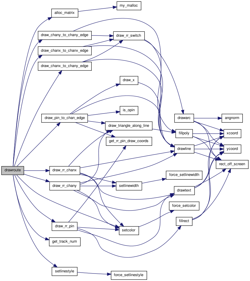
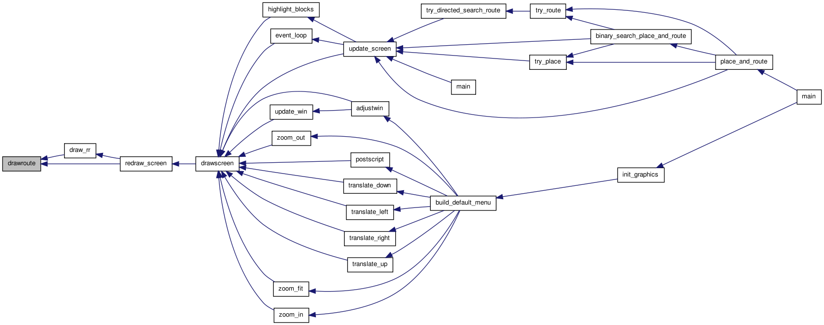
| static void drawroute | ( | enum e_draw_net_type | draw_net_type | ) | [static] |
Definition at line 1583 of file draw.c.
01584 {
01585
01586     /* Draws the nets in the positions fixed by the router.  If draw_net_type is *
01587      * ALL_NETS, draw all the nets.  If it is HIGHLIGHTED, draw only the nets    *
01588      * that are not coloured black (useful for drawing over the rr_graph).       */
01589
01590     /* Next free track in each channel segment if routing is GLOBAL */
01591
01592     static int **chanx_track = NULL;    /* [1..nx][0..ny] */
01593     static int **chany_track = NULL;    /* [0..nx][1..ny] */
01594
01595     int inet, i, j, inode, prev_node, prev_track, itrack;
01596     short switch_type;
01597     struct s_trace *tptr;
01598     t_rr_type rr_type, prev_type;
01599
01600
01601     if(draw_route_type == GLOBAL)
01602         {
01603             /* Allocate some temporary storage if it's not already available. */
01604             if(chanx_track == NULL)
01605                 {
01606                     chanx_track =
01607                         (int **)alloc_matrix(1, nx, 0, ny, sizeof(int));
01608                 }
01609
01610             if(chany_track == NULL)
01611                 {
01612                     chany_track =
01613                         (int **)alloc_matrix(0, nx, 1, ny, sizeof(int));
01614                 }
01615
01616             for(i = 1; i <= nx; i++)
01617                 for(j = 0; j <= ny; j++)
01618                     chanx_track[i][j] = (-1);
01619
01620             for(i = 0; i <= nx; i++)
01621                 for(j = 1; j <= ny; j++)
01622                     chany_track[i][j] = (-1);
01623         }
01624
01625     setlinestyle(SOLID);
01626
01627 /* Now draw each net, one by one.      */
01628
01629     for(inet = 0; inet < num_nets; inet++)
01630         {
01631             if(net[inet].is_global)     /* Don't draw global nets. */
01632                 continue;
01633
01634             if(trace_head[inet] == NULL)        /* No routing.  Skip.  (Allows me to draw */
01635                 continue;       /* partially complete routes).            */
01636
01637             if(draw_net_type == HIGHLIGHTED && net_color[inet] == BLACK)
01638                 continue;
01639
01640             setcolor(net_color[inet]);
01641             tptr = trace_head[inet];    /* SOURCE to start */
01642             inode = tptr->index;
01643             rr_type = rr_node[inode].type;
01644
01645
01646             for(;;)
01647                 {
01648                     prev_node = inode;
01649                     prev_type = rr_type;
01650                     switch_type = tptr->iswitch;
01651                     tptr = tptr->next;
01652                     inode = tptr->index;
01653                     rr_type = rr_node[inode].type;
01654
01655                     switch (rr_type)
01656                         {
01657
01658                         case OPIN:
01659                             draw_rr_pin(inode, net_color[inet]);
01660                             break;
01661
01662                         case IPIN:
01663                             draw_rr_pin(inode, net_color[inet]);
01664                             prev_track =
01665                                 get_track_num(prev_node, chanx_track,
01666                                               chany_track);
01667                             draw_pin_to_chan_edge(inode, prev_node);
01668                             break;
01669
01670                         case CHANX:
01671                             if(draw_route_type == GLOBAL)
01672                                 chanx_track[rr_node[inode].
01673                                             xlow][rr_node[inode].ylow]++;
01674
01675                             itrack =
01676                                 get_track_num(inode, chanx_track,
01677                                               chany_track);
01678                             draw_rr_chanx(inode, itrack);
01679
01680                             switch (prev_type)
01681                                 {
01682
01683                                 case CHANX:
01684                                     prev_track =
01685                                         get_track_num(prev_node, chanx_track,
01686                                                       chany_track);
01687                                     draw_chanx_to_chanx_edge(prev_node,
01688                                                              prev_track,
01689                                                              inode, itrack,
01690                                                              switch_type);
01691                                     break;
01692
01693                                 case CHANY:
01694                                     prev_track =
01695                                         get_track_num(prev_node, chanx_track,
01696                                                       chany_track);
01697                                     draw_chanx_to_chany_edge(inode, itrack,
01698                                                              prev_node,
01699                                                              prev_track,
01700                                                              FROM_Y_TO_X,
01701                                                              switch_type);
01702                                     break;
01703
01704                                 case OPIN:
01705                                     draw_pin_to_chan_edge(prev_node, inode);
01706                                     break;
01707
01708                                 default:
01709                                     printf
01710                                         ("Error in drawroute:  Unexpected connection from an \n"
01711                                          "rr_node of type %d to one of type %d.\n",
01712                                          prev_type, rr_type);
01713                                     exit(1);
01714                                 }
01715
01716                             break;
01717
01718                         case CHANY:
01719                             if(draw_route_type == GLOBAL)
01720                                 chany_track[rr_node[inode].
01721                                             xlow][rr_node[inode].ylow]++;
01722
01723                             itrack =
01724                                 get_track_num(inode, chanx_track,
01725                                               chany_track);
01726                             draw_rr_chany(inode, itrack);
01727
01728                             switch (prev_type)
01729                                 {
01730
01731                                 case CHANX:
01732                                     prev_track =
01733                                         get_track_num(prev_node, chanx_track,
01734                                                       chany_track);
01735                                     draw_chanx_to_chany_edge(prev_node,
01736                                                              prev_track,
01737                                                              inode, itrack,
01738                                                              FROM_X_TO_Y,
01739                                                              switch_type);
01740                                     break;
01741
01742                                 case CHANY:
01743                                     prev_track =
01744                                         get_track_num(prev_node, chanx_track,
01745                                                       chany_track);
01746                                     draw_chany_to_chany_edge(prev_node,
01747                                                              prev_track,
01748                                                              inode, itrack,
01749                                                              switch_type);
01750                                     break;
01751
01752                                 case OPIN:
01753                                     draw_pin_to_chan_edge(prev_node, inode);
01754
01755                                     break;
01756
01757                                 default:
01758                                     printf
01759                                         ("Error in drawroute:  Unexpected connection from an \n"
01760                                          "rr_node of type %d to one of type %d.\n",
01761                                          prev_type, rr_type);
01762                                     exit(1);
01763                                 }
01764
01765                             break;
01766
01767                         default:
01768                             break;
01769
01770                         }
01771
01772                     if(rr_type == SINK)
01773                         {       /* Skip the next segment */
01774                             tptr = tptr->next;
01775                             if(tptr == NULL)
01776                                 break;
01777                             inode = tptr->index;
01778                             rr_type = rr_node[inode].type;
01779                         }
01780
01781                 }               /* End loop over traceback. */
01782         }                       /* End for (each net) */
01783 }
| static void drawscreen | ( | void | ) | [static] |
Definition at line 252 of file draw.c.
00253 {
00254
00255     /* This is the screen redrawing routine that event_loop assumes exists.  *
00256      * It erases whatever is on screen, then calls redraw_screen to redraw   *
00257      * it.                                                                   */
00258
00259     clearscreen();
00260     redraw_screen();
00261 }
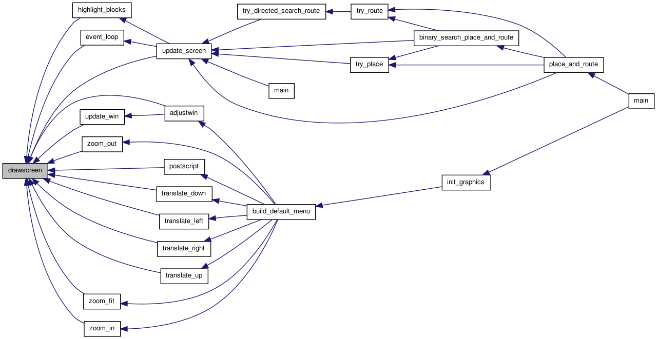
| static void get_block_center | ( | int | bnum, | |
| float * | x, | |||
| float * | y | |||
| ) | [static] |
Definition at line 677 of file draw.c.
00680 {
00681
00682     /* This routine finds the center of block bnum in the current placement, *
00683      * and returns it in *x and *y.  This is used in routine shownets.       */
00684
00685     int i, j, k;
00686     float sub_tile_step;
00687
00688     i = block[bnum].x;
00689     j = block[bnum].y;
00690     k = block[bnum].z;
00691
00692     sub_tile_step = tile_width / block[bnum].type->capacity;
00693
00694     if((i < 1) || (i > nx))
00695         {                       /* Left and right fringe */
00696             *x = tile_x[i] + (sub_tile_step * (k + 0.5));
00697         }
00698     else
00699         {
00700             *x = tile_x[i] + (tile_width / 2.0);
00701         }
00702
00703     if((j < 1) || (j > ny))
00704         {                       /* Top and bottom fringe */
00705             *y = tile_y[j] + (sub_tile_step * (k + 0.5));
00706         }
00707     else
00708         {
00709             *y = tile_y[j] + (tile_width / 2.0);
00710         }
00711 }
| static void get_rr_pin_draw_coords | ( | int | inode, | |
| int | iside, | |||
| int | ioff, | |||
| float * | xcen, | |||
| float * | ycen | |||
| ) | [static] |
Definition at line 1517 of file draw.c.
01522 {
01523
01524     /* Returns the coordinates at which the center of this pin should be drawn. *
01525      * inode gives the node number, and iside gives the side of the clb or pad  *
01526      * the physical pin is on.                                                  */
01527
01528     int i, j, k, ipin, pins_per_sub_tile;
01529     float offset, xc, yc, step;
01530     t_type_ptr type;
01531
01532     i = rr_node[inode].xlow;
01533     j = rr_node[inode].ylow + ioff;     /* Need correct tile of block */
01534
01535     xc = tile_x[i];
01536     yc = tile_y[j];
01537
01538     ipin = rr_node[inode].ptc_num;
01539     type = grid[i][j].type;
01540     pins_per_sub_tile = grid[i][j].type->num_pins / grid[i][j].type->capacity;
01541     k = ipin / pins_per_sub_tile;
01542
01543     /* Since pins numbers go across all sub_tiles in a block in order
01544      * we can treat as a block box for this step */
01545
01546     /* For each sub_tile we need and extra padding space */
01547     step = (float)(tile_width) / (float)(type->num_pins + type->capacity);
01548     offset = (ipin + k + 1) * step;
01549
01550     switch (iside)
01551         {
01552         case LEFT:
01553             yc += offset;
01554             break;
01555
01556         case RIGHT:
01557             xc += tile_width;
01558             yc += offset;
01559             break;
01560
01561         case BOTTOM:
01562             xc += offset;
01563             break;
01564
01565         case TOP:
01566             xc += offset;
01567             yc += tile_width;
01568             break;
01569
01570         default:
01571             printf("Error in get_rr_pin_draw_coords:  Unexpected iside %d.\n",
01572                    iside);
01573             exit(1);
01574             break;
01575         }
01576
01577     *xcen = xc;
01578     *ycen = yc;
01579 }
| static int get_track_num | ( | int | inode, | |
| int ** | chanx_track, | |||
| int ** | chany_track | |||
| ) | [static] |
Definition at line 1787 of file draw.c.
01790 {
01791
01792 /* Returns the track number of this routing resource node.   */
01793
01794     int i, j;
01795     t_rr_type rr_type;
01796
01797     if(draw_route_type == DETAILED)
01798         return (rr_node[inode].ptc_num);
01799
01800 /* GLOBAL route stuff below. */
01801
01802     rr_type = rr_node[inode].type;
01803     i = rr_node[inode].xlow;    /* NB: Global rr graphs must have only unit */
01804     j = rr_node[inode].ylow;    /* length channel segments.                 */
01805
01806     switch (rr_type)
01807         {
01808         case CHANX:
01809             return (chanx_track[i][j]);
01810
01811         case CHANY:
01812             return (chany_track[i][j]);
01813
01814         default:
01815             printf
01816                 ("Error in get_track_num:  unexpected node type %d for node %d."
01817                  "\n", rr_type, inode);
01818             exit(1);
01819         }
01820 }
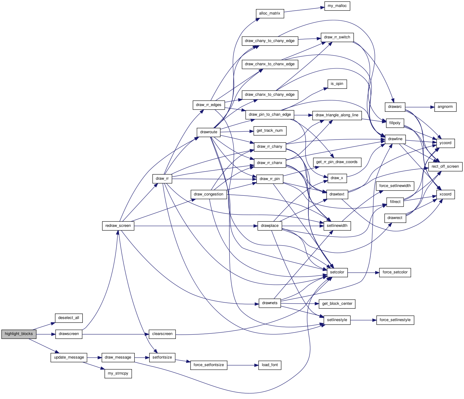
| static void highlight_blocks | ( | float | x, | |
| float | y | |||
| ) | [static] |
Definition at line 1824 of file draw.c.
01826 {
01827
01828     /* This routine is called when the user clicks in the graphics area. *
01829      * It determines if a clb was clicked on.  If one was, it is         *
01830      * highlighted in green, it's fanin nets and clbs are highlighted in *
01831      * blue and it's fanout is highlighted in red.  If no clb was        *
01832      * clicked on (user clicked on white space) any old highlighting is  *
01833      * removed.  Note that even though global nets are not drawn, their  *
01834      * fanins and fanouts are highlighted when you click on a block      *
01835      * attached to them.                                                 */
01836
01837     int i, j, k, hit, bnum, ipin, netnum, fanblk;
01838     int iclass;
01839     float io_step;
01840     t_type_ptr type;
01841     char msg[BUFSIZE];
01842
01843     deselect_all();
01844
01845     hit = 0;
01846     for(i = 0; i <= (nx + 1) && !hit; i++)
01847         {
01848             if(x <= tile_x[i] + tile_width)
01849                 {
01850                         if(x >= tile_x[i]){
01851                             for(j = 0; j <= (ny + 1) && !hit; j++)
01852                                 {
01853                                         if(grid[i][j].offset != 0)
01854                                                 continue;
01855                                         type = grid[i][j].type;
01856                                         if(y <= tile_y[j + type->height - 1] + tile_width)
01857                                         {
01858                                                 if(y >= tile_y[j])
01859                                                         hit = 1;
01860                                         }
01861                                 }
01862
01863                         }
01864                 }
01865         }
01866         i--;
01867         j--;
01868
01869     if(!hit)
01870         {
01871             update_message(default_message);
01872             drawscreen();
01873             return;
01874         }
01875     type = grid[i][j].type;
01876     hit = 0;
01877
01878     if(EMPTY_TYPE == type)
01879         {
01880             update_message(default_message);
01881             drawscreen();
01882             return;
01883         }
01884
01885     /* The user selected the clb at location (i,j). */
01886     io_step = tile_width / type->capacity;
01887
01888     if((i < 1) || (i > nx))     /* Vertical columns of IOs */
01889         k = (int)((y - tile_y[j]) / io_step);
01890     else
01891         k = (int)((x - tile_x[i]) / io_step);
01892
01893     assert(k < type->capacity);
01894     if(grid[i][j].blocks[k] == EMPTY)
01895         {
01896             update_message(default_message);
01897             drawscreen();
01898             return;
01899         }
01900     bnum = grid[i][j].blocks[k];
01901
01902     /* Highlight fanin and fanout. */
01903
01904     for(k = 0; k < type->num_pins; k++)
01905         {                       /* Each pin on a FB */
01906             netnum = block[bnum].nets[k];
01907
01908             if(netnum == OPEN)
01909                 continue;
01910
01911             iclass = type->pin_class[k];
01912
01913             if(type->class_inf[iclass].type == DRIVER)
01914                 {               /* Fanout */
01915                     net_color[netnum] = RED;
01916                     for(ipin = 1; ipin <= net[netnum].num_sinks; ipin++)
01917                         {
01918                             fanblk = net[netnum].node_block[ipin];
01919                             block_color[fanblk] = RED;
01920                         }
01921                 }
01922             else
01923                 {               /* This net is fanin to the block. */
01924                     net_color[netnum] = BLUE;
01925                     fanblk = net[netnum].node_block[0]; /* DRIVER to net */
01926                     block_color[fanblk] = BLUE;
01927                 }
01928         }
01929
01930     block_color[bnum] = GREEN;  /* Selected block. */
01931
01932     sprintf(msg, "Block %d (%s) at (%d, %d) selected.", bnum,
01933             block[bnum].name, i, j);
01934     update_message(msg);
01935     drawscreen();               /* Need to erase screen. */
01936 }

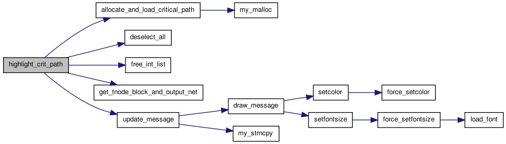
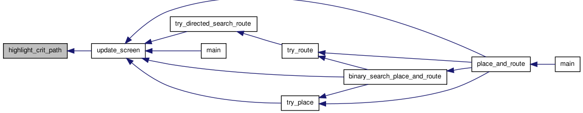
| static void highlight_crit_path | ( | void(*)(void) | drawscreen_ptr | ) | [static] |
Definition at line 376 of file draw.c.
00377 {
00378
00379     /* Highlights all the blocks and nets on the critical path. */
00380
00381     t_linked_int *critical_path_head, *critical_path_node;
00382     int inode, iblk, inet, num_nets_seen;
00383     static int nets_to_highlight = 1;
00384     char msg[BUFSIZE];
00385
00386     if(nets_to_highlight == 0)
00387         {                       /* Clear the display of all highlighting. */
00388             nets_to_highlight = 1;
00389             deselect_all();
00390             update_message(default_message);
00391             drawscreen_ptr();
00392             return;
00393         }
00394
00395     critical_path_head = allocate_and_load_critical_path();
00396     critical_path_node = critical_path_head;
00397     num_nets_seen = 0;
00398
00399     while(critical_path_node != NULL)
00400         {
00401             inode = critical_path_node->data;
00402             get_tnode_block_and_output_net(inode, &iblk, &inet);
00403
00404             if(num_nets_seen == nets_to_highlight)
00405                 {               /* Last block */
00406                     block_color[iblk] = MAGENTA;
00407                 }
00408             else if(num_nets_seen == nets_to_highlight - 1)
00409                 {               /* 2nd last block */
00410                     block_color[iblk] = YELLOW;
00411                 }
00412             else if(num_nets_seen < nets_to_highlight)
00413                 {               /* Earlier block */
00414                     block_color[iblk] = DARKGREEN;
00415                 }
00416
00417             if(inet != OPEN)
00418                 {
00419                     num_nets_seen++;
00420
00421                     if(num_nets_seen < nets_to_highlight)
00422                         {       /* First nets. */
00423                             net_color[inet] = DARKGREEN;
00424                         }
00425                     else if(num_nets_seen == nets_to_highlight)
00426                         {
00427                             net_color[inet] = CYAN;     /* Last (new) net. */
00428                         }
00429                 }
00430
00431             critical_path_node = critical_path_node->next;
00432         }
00433
00434     if(nets_to_highlight == num_nets_seen)
00435         {
00436             nets_to_highlight = 0;
00437             sprintf(msg, "All %d nets on the critical path highlighted.",
00438                     num_nets_seen);
00439         }
00440     else
00441         {
00442             sprintf(msg, "First %d nets on the critical path highlighted.",
00443                     nets_to_highlight);
00444             nets_to_highlight++;
00445         }
00446
00447     free_int_list(&critical_path_head);
00448
00449     update_message(msg);
00450     drawscreen_ptr();
00451 }
| void init_draw_coords | ( | float | width_val | ) |
Definition at line 475 of file draw.c.
00476 {
00477
00478     /* Load the arrays containing the left and bottom coordinates of the clbs   *
00479      * forming the FPGA.  tile_width_val sets the width and height of a drawn    *
00480      * clb.                                                                     */
00481
00482     int i;
00483     int j;
00484
00485     if(!show_graphics)
00486         return;                 /* -nodisp was selected. */
00487
00488     tile_width = width_val;
00489     pin_size = 0.3;
00490     for(i = 0; i < num_types; ++i)
00491         {
00492             pin_size =
00493                 min(pin_size,
00494                     (tile_width / (4.0 * type_descriptors[i].num_pins)));
00495         }
00496
00497     j = 0;
00498     for(i = 0; i < (nx + 1); i++)
00499         {
00500             tile_x[i] = (i * tile_width) + j;
00501             j += chan_width_y[i] + 1;   /* N wires need N+1 units of space */
00502         }
00503     tile_x[nx + 1] = ((nx + 1) * tile_width) + j;
00504
00505     j = 0;
00506     for(i = 0; i < (ny + 1); ++i)
00507         {
00508             tile_y[i] = (i * tile_width) + j;
00509             j += chan_width_x[i] + 1;
00510         }
00511     tile_y[ny + 1] = ((ny + 1) * tile_width) + j;
00512
00513     init_world(0.0,
00514                tile_y[ny + 1] + tile_width, tile_x[nx + 1] + tile_width, 0.0);
00515 }
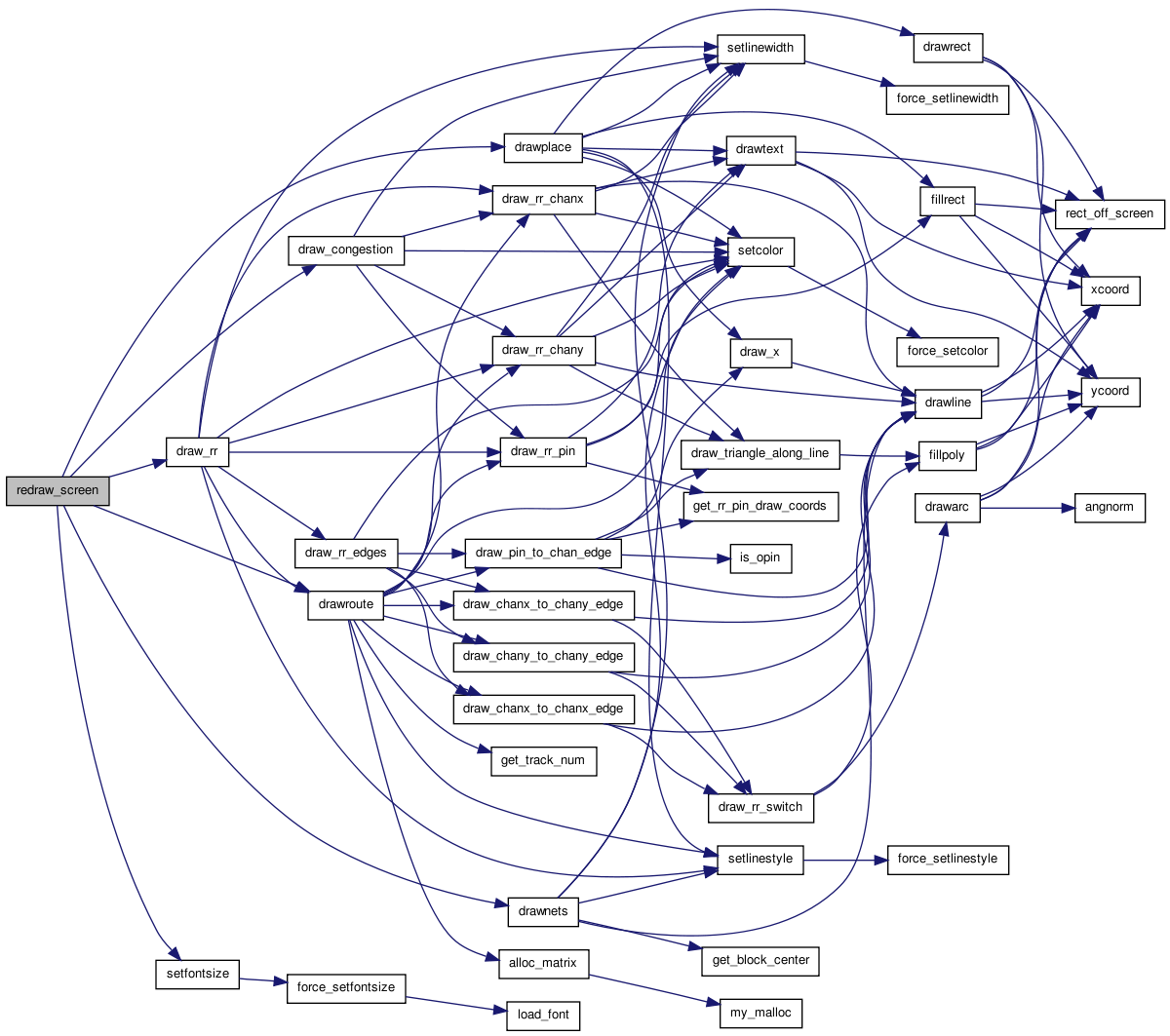
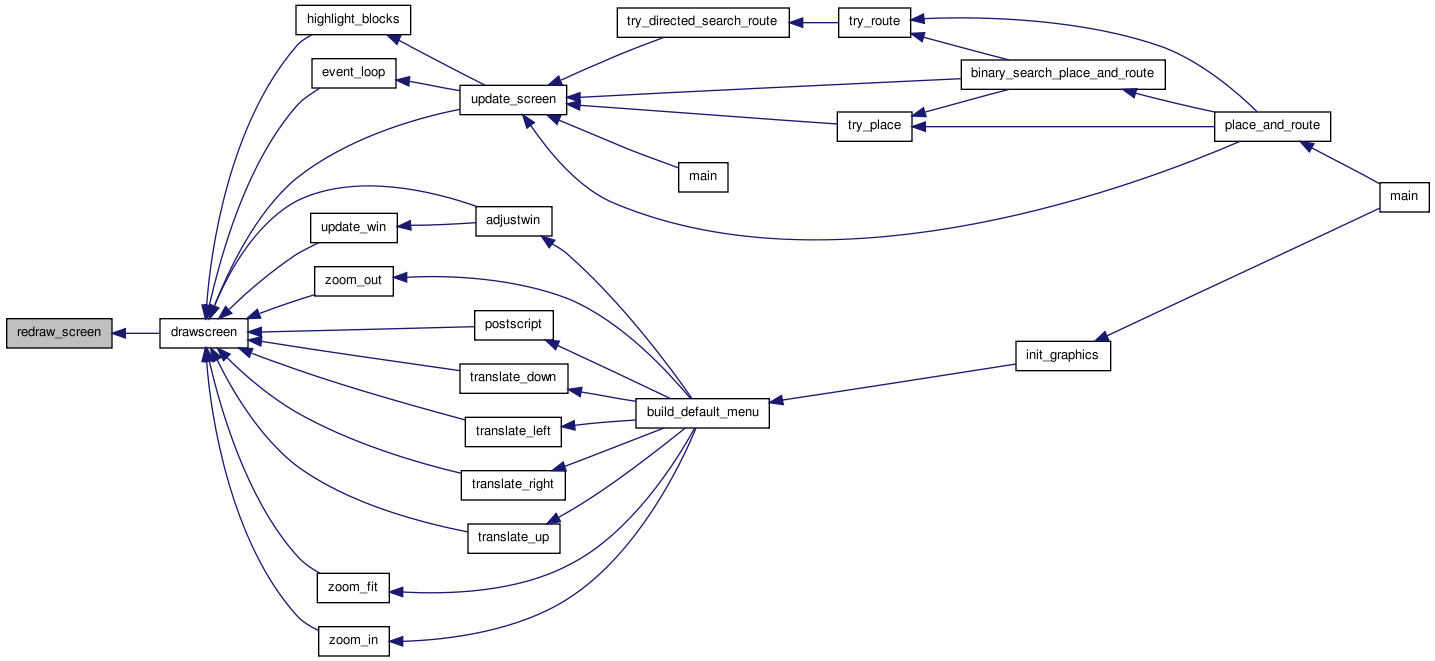
| static void redraw_screen | ( | void | ) | [static] |
Definition at line 265 of file draw.c.
00266 {
00267
00268     /* The screen redrawing routine called by drawscreen and           *
00269      * highlight_blocks.  Call this routine instead of drawscreen if   *
00270      * you know you don't need to erase the current graphics, and want *
00271      * to avoid a screen "flash".                                      */
00272
00273     setfontsize(20);            /* UDSD Modification by WMF */
00274     if(pic_on_screen == PLACEMENT)
00275         {
00276             drawplace();
00277             if(show_nets)
00278                 {
00279                     drawnets();
00280                 }
00281         }
00282     else
00283         {                       /* ROUTING on screen */
00284             drawplace();
00285
00286             if(show_nets)
00287                 {
00288                     drawroute(ALL_NETS);
00289                 }
00290             else
00291                 {
00292                     draw_rr();
00293                 }
00294
00295             if(show_congestion)
00296                 {
00297                     draw_congestion();
00298                 }
00299         }
00300 }
| void set_graphics_state | ( | boolean | show_graphics_val, | |
| int | gr_automode_val, | |||
| enum e_route_type | route_type | |||
| ) |
Definition at line 155 of file draw.c.
00158 {
00159
00160     /* Sets the static show_graphics and gr_automode variables to the    *
00161      * desired values.  They control if graphics are enabled and, if so, *
00162      * how often the user is prompted for input.                         */
00163
00164     show_graphics = show_graphics_val;
00165     gr_automode = gr_automode_val;
00166     draw_route_type = route_type;
00167 }

| static void toggle_congestion | ( | void(*)(void) | drawscreen | ) | [static] |
Definition at line 341 of file draw.c.
00342 {
00343
00344     /* Turns the congestion display on and off.   */
00345     char msg[BUFSIZE];
00346     int inode, num_congested;
00347
00348     show_nets = FALSE;
00349     draw_rr_toggle = DRAW_NO_RR;
00350     show_congestion = !show_congestion;
00351
00352     if(!show_congestion)
00353         {
00354             update_message(default_message);
00355         }
00356     else
00357         {
00358             num_congested = 0;
00359             for(inode = 0; inode < num_rr_nodes; inode++)
00360                 {
00361                     if(rr_node[inode].occ > rr_node[inode].capacity)
00362                         {
00363                             num_congested++;
00364                         }
00365                 }
00366
00367             sprintf(msg, "%d routing resources are overused.", num_congested);
00368             update_message(msg);
00369         }
00370
00371     drawscreen_ptr();
00372 }

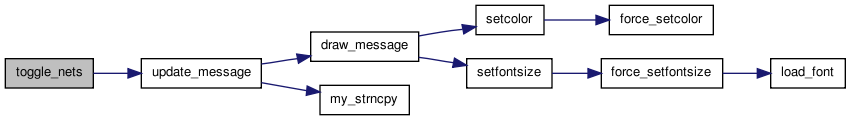
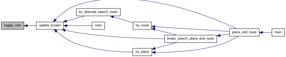
| static void toggle_nets | ( | void(*)(void) | drawscreen | ) | [static] |
Definition at line 304 of file draw.c.
00305 {
00306
00307     /* Enables/disables drawing of nets when a the user clicks on a button.    *
00308      * Also disables drawing of routing resources.  See graphics.c for details *
00309      * of how buttons work.                                                    */
00310
00311     show_nets = !show_nets;
00312     draw_rr_toggle = DRAW_NO_RR;
00313     show_congestion = FALSE;
00314
00315     update_message(default_message);
00316     drawscreen_ptr();
00317 }
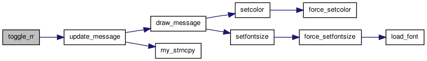
| static void toggle_rr | ( | void(*)(void) | drawscreen | ) | [static] |
Definition at line 321 of file draw.c.
00322 {
00323
00324     /* Cycles through the options for viewing the routing resources available   *
00325      * in an FPGA.  If a routing isn't on screen, the routing graph hasn't been *
00326      * built, and this routine doesn't switch the view. Otherwise, this routine *
00327      * switches to the routing resource view.  Clicking on the toggle cycles    *
00328      * through the options:  DRAW_NO_RR, DRAW_ALL_RR, DRAW_ALL_BUT_BUFFERS_RR,  *
00329      * DRAW_NODES_AND_SBOX_RR, and DRAW_NODES_RR.                               */
00330
00331     draw_rr_toggle = (draw_rr_toggle + 1) % (DRAW_RR_TOGGLE_MAX);
00332     show_nets = FALSE;
00333     show_congestion = FALSE;
00334
00335     update_message(default_message);
00336     drawscreen_ptr();
00337 }
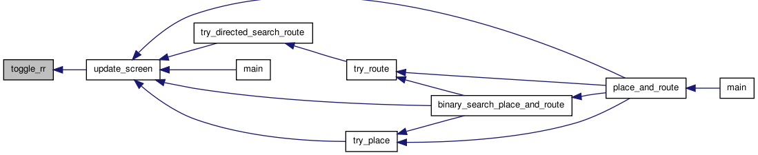
| void update_screen | ( | int | priority, | |
| char * | msg, | |||
| enum pic_type | pic_on_screen_val, | |||
| boolean | crit_path_button_enabled | |||
| ) |
Definition at line 171 of file draw.c.
00175 {
00176
00177     /* Updates the screen if the user has requested graphics.  The priority  *
00178      * value controls whether or not the Proceed button must be clicked to   *
00179      * continue.  Saves the pic_on_screen_val to allow pan and zoom redraws. */
00180
00181     if(!show_graphics)          /* Graphics turned off */
00182         return;
00183
00184
00185
00186     /* If it's the type of picture displayed has changed, set up the proper  *
00187      * buttons.                                                              */
00188     if(pic_on_screen != pic_on_screen_val)
00189         {
00190             if(pic_on_screen_val == PLACEMENT && pic_on_screen == NO_PICTURE)
00191                 {
00192                     create_button("Window", "Toggle Nets", toggle_nets);
00193                 }
00194             else if(pic_on_screen_val == ROUTING
00195                     && pic_on_screen == PLACEMENT)
00196                 {
00197                     create_button("Toggle Nets", "Toggle RR", toggle_rr);
00198                     create_button("Toggle RR", "Congestion",
00199                                   toggle_congestion);
00200
00201                     if(crit_path_button_enabled)
00202                         {
00203                             create_button("Congestion", "Crit. Path",
00204                                           highlight_crit_path);
00205                         }
00206                 }
00207             else if(pic_on_screen_val == PLACEMENT
00208                     && pic_on_screen == ROUTING)
00209                 {
00210                     destroy_button("Toggle RR");
00211                     destroy_button("Congestion");
00212
00213                     if(crit_path_button_enabled)
00214                         {
00215                             destroy_button("Crit. Path");
00216                         }
00217                 }
00218             else if(pic_on_screen_val == ROUTING
00219                     && pic_on_screen == NO_PICTURE)
00220                 {
00221                     create_button("Window", "Toggle Nets", toggle_nets);
00222                     create_button("Toggle Nets", "Toggle RR", toggle_rr);
00223                     create_button("Toggle RR", "Congestion",
00224                                   toggle_congestion);
00225
00226                     if(crit_path_button_enabled)
00227                         {
00228                             create_button("Congestion", "Crit. Path",
00229                                           highlight_crit_path);
00230                         }
00231                 }
00232         }
00233     /* Save the main message. */
00234
00235     my_strncpy(default_message, msg, BUFSIZE);
00236
00237     pic_on_screen = pic_on_screen_val;
00238     update_message(msg);
00239     drawscreen();
00240     if(priority >= gr_automode)
00241         {
00242             event_loop(highlight_blocks, drawscreen);
00243         }
00244     else
00245         {
00246             flushinput();
00247         }
00248 }
Variable Documentation
char default_message[BUFSIZE] [static] |
enum e_route_type draw_route_type [static] |
enum e_draw_rr_toggle draw_rr_toggle = DRAW_NO_RR [static] |
int gr_automode [static] |
enum pic_type pic_on_screen = NO_PICTURE [static] |
boolean show_congestion = FALSE [static] |
boolean show_graphics [static] |
float tile_width [static] |