Defining the Instrument States for S-Parameter Measurements
IC-CAP provides remote control of the DC source/monitor and the network analyzer to measure the device under test. These procedures configure IC-CAP with both the DC source/monitor and the Agilent 8753 network analyzer instrument states for S-parameter measurements. The first procedure sets the instrument states for a broadband swept-frequency measurement, and the second for a CW measurement.
Instrument States for Swept Frequency Measurements
Use this procedure if you have been referred here from one of the device modeling chapters.
You will need to set the instrument states separately for each measurement setup in a modeling procedure. However, use the same settings for all the swept S-parameter measurement setups in one model (except that Integ Time can differ among setups). Unless you use the example settings documented here, write down the settings you use, to duplicate among setups within one model.
The settings used here are examples. Your settings may differ. Explanations here apply to all swept-frequency S-parameter measurements in the different device measurement procedures.
|
Note
|
|
|
|
|
Source parameters such as frequency range are not set in this procedure, but in the individual S-parameter setup procedures in each model chapter.
Do not use these settings for a CW S-parameter measurement. The settings for a CW measurement are slightly different, and are documented following this procedure.
|
|
| 1 |
Select the swept S-parameter setup of your choice. |
| 2 |
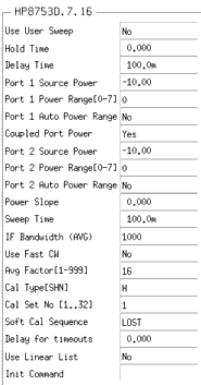
Select the Instrument Options tab, and a window will be displayed showing the instrument states. The following figure shows an example. |
Figure 204 Instrument States for Swept Frequency Measurements with Agilent 8753D
|

|
| 3 |
Set the Agilent 4142 instrument state the same as for the DC measurements. |
| 4 |
Set the Agilent 8753 instrument state according to the actual hardware configuration, the calibration used, and the device to be measured, following these guidelines: |
| 5 |
Set Use User Sweep to No, because this is a standard internal sweep. |
| 6 |
Hold Time is the time in seconds before the instrument starts a sweep, to allow for DC settling. Generally, no hold time is required. |
| 7 |
Delay Time is the delay in seconds the instrument waits before setting each frequency. No delay is needed here, but the default is 100 ms. |
| 8 |
Port 1 Source Power and Port 2 Source Power are used with an analyzer that has an integrated test set. Set the power to the same level as in the network analyzer calibration. Take care that the power level will not be excessive at the device input or at the input port samplers of the analyzer. The default is -10 dBm. |
| 9 |
Port 1 Power Range and Port 2 Power Range are used with an analyzer that has an integrated test set. The synthesized source in the analyzer contains a programmable step attenuator with eight power ranges. This lets you determine which range is used: the default is 0. |
| 10 |
Port 1 and Port 2 Auto Power Range are used with an analyzer that has an integrated test set. These settings enable an autoranging power level and attenuation capability. The default IC-CAP setting is No. |
| 11 |
Coupled Port Power is used with an analyzer that has an integrated test set. It couples port 2 to the port 1 power settings, ignoring the settings for port 2. The default is Yes, to couple the ports together. |
| 12 |
If you calibrate with a power slope, set the corresponding value for Power Slope here, to better view the response of a device with power drop-off at higher frequencies. The units for power slope are dB/GHz; the default value is 0.000. (A network analyzer message will caution you that the correction may be invalid, but this can be ignored.) |
| 13 |
Set the same Sweep Time as in the network analyzer calibration. You can check this on the network analyzer in LOCAL mode by pressing MENU > SWEEP TIME. If you set a reduced IF bandwidth for calibration, the sweep time may have been slowed down automatically. |
| 14 |
Set IF Bandwidth to the same value as in the calibration. The noise floor can be reduced by reducing the receiver input bandwidth. |
| 15 |
Set Use Fast CW to No, because fast CW is not compatible with the instrument calibration. |
| 16 |
Set Avg Factor to the same averaging factor you set in the calibration. |
| 17 |
Set Cal Type to H (hardware) so that IC-CAP will recognize calibration device measurements at the network analyzer front panel. |
| 18 |
Cal Set No must be set to the analyzer register number where you store your swept broadband calibration. Do not use register 6, which stores the active instrument state. |
| 19 |
Soft Cal Sequence refers to the sequence of measurements of the cal standard devices: load-open-short-thru. You can set a different sequence if you prefer. |
| 20 |
Delay for Timeouts increases the timeout and wait times. It can generally be set to the default value of 0.000. |
| 21 |
If you define a specific number of points for the measurement calibration, set Use Linear List to No, the normal setting for a swept measurement. The setting would be Yes for a log or list sweep. |
| 22 |
If necessary, refer to the "Application and Operation Concepts" chapter of the Agilent 8753C Operating Manual for more detail. |
| 23 |
Close the instrument options window. Then return to the modeling procedure. |
Different Settings for Agilent 8753 with External Test Set
An Agilent 8753 with an external test set uses different settings for power level and attenuation. Also, these analyzers do not have the power autoranging or coupled port power functions. These are the different settings:
| 1 |
Port 1 Atten and Port 2 Atten must be set to the same level of attenuation you set in the network analyzer calibration. The default is 20 dB. |
| 2 |
Source Power must be set to the same level as in the network analyzer calibration. The default is -10 dBm. |
Instrument States for CW Frequency Measurements
Use this procedure if you have been referred here from one of the device modeling chapters.
You will need to set the instrument states separately for each measurement setup in a modeling procedure. However, use the same settings for all the CW S-parameter measurement setups in one model (except that Integ Time can differ among setups). Unless you use the settings documented here, write down the settings you use, to duplicate among setups within one model.
The settings used here are examples. Your settings may differ. Explanations here apply to all CW S-parameter measurements in the different device measurement procedures.
| 1 |
Select the CW S-parameter setup of your choice. |
| 2 |
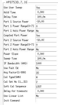
Select the Instrument Options tab and a window will be displayed showing the instrument states. The following figure shows an example. |
Figure 205 Instrument States for CW Frequency Measurements with
Agilent 8753D
|

|
| 3 |
Set the Agilent 4142 instrument states the same as for the DC measurements. |
|
Note
|
|
|
|
|
The network analyzer instrument state settings for a CW-frequency S-parameter measurement are the same as for a swept S-parameter measurement, with the following exceptions:
|
|
| 4 |
Set Use User Sweep to Yes because CW is a nonstandard sweep. |
| 5 |
Be sure to set the source power and attenuation levels the same as in the network analyzer calibration. |
| 6 |
Set Cal Set No to the analyzer register number where you stored your CW calibration. This must be different from the register used by the swept broadband calibration, and from any other CW calibration you make at a different frequency for any different measurement. |
| 7 |
You can set Use Linear List to either Yes or No. This setting is ignored by IC-CAP for a CW measurement. |
| 8 |
Close the instrument options window. Then return to the modeling procedure. |
|

