Defining the DC Source/Monitor Instrument State
IC-CAP provides remote control of the DC source/monitor and the network analyzer to measure the device under test. This procedure configures IC-CAP with the instrument state settings (instrument options) for the DC source/monitor.
Use this procedure if you have been referred here from one of the device modeling procedures.
You will need to set the DC source/monitor instrument state separately for each DC or DC-biased measurement setup in a modeling procedure. However, use the same settings for all the measurement setups in one model (except that Integ Time can differ among setups). Unless you use the default settings documented here, it is helpful to write down the settings to duplicate in the other setups.
|
Note
|
|
|
|
|
DC signal levels and other input parameters that differ among measurement setups are not set in this procedure, but in the individual setup procedures in each model chapter.
|
|
The settings used in this procedure are defaults and the explanations are general.
| 1 |
Select the DC measurement setup of your choice. |
| 2 |
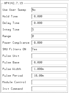
Select the Instrument Options tab, and a window will be displayed showing the instrument states for the DC source/monitor. Figure 203 illustrates example DC source/monitor instrument states. |
| 3 |
Set each of the DC source/monitor measurement parameters according to the actual Agilent 4142 configuration and the device to be measured, using the guidelines in the following steps. |
Figure 203 Example Agilent 4142 DC Source/Monitor Instrument State
|

|
| 4 |
Set Use User Sweep to No, as it is unnecessary for these procedures, and the source/monitor internal sweep is faster. |
| 5 |
Hold Time is the delay in seconds before starting a sweep, to allow for DC settling. Generally, no hold time is required. |
| 6 |
Delay Time is the time in seconds the instrument waits before taking a measurement at each step of a sweep. Generally no delay time is needed. |
| 7 |
For Integ Time, M (medium) is a good default choice. In measurements where a long integration time is needed for noise reduction, you would use L (long), and you will be instructed to do so in certain procedures. You can speed up a measurement by using S (short), but this is not recommended because it degrades the dynamic range of the measurement. |
| 8 |
Set Range to 0 to implement SMU autoranging. |
| 9 |
Power Compliance is used to set the maximum current/voltage combination for the DC source/monitor. However, in the models, SMU voltage and current compliances are set individually in the individual setups. Therefore the value here can be set to 0.000. |
| 10 |
Set SMU Filters ON to Yes. This switches in low-pass filters on the SMU outputs, to protect the device from voltage spikes caused by DAC output changes. |
| 11 |
High-frequency IC-CAP is not generally configured for pulsed measurements, therefore Pulse Unit can be left blank. All other Pulse settings are then irrelevant and can be ignored. |
| 12 |
Module Control is not used in these procedures: leave the field blank. |
| 13 |
Init Command sets the instrument to a mode not supported by other fields in this table. It is not generally used in these models. Leave the field blank unless instructed otherwise. |
| 14 |
If you wish, refer to the DC source/monitor manual for more detail. |
| 15 |
If the measurement setup you are configuring calls for a DC measurement only, close the instrument options window. Then return to the modeling procedure. |
|
