Print version of this Book (PDF file)
Calibrating the Network Analyzer
The network analyzer must be calibrated before any S-parameter measurements are performed. The system must be allowed to warm up for at least 1 hour before calibration, and the calibration standards must be at ambient room temperature. It is convenient to switch on the analyzer and expose the calibration devices to air before you make the DC measurements.
Good calibration of the network analyzer system is critical to a good high-frequency measurement and extraction. A good calibration is dependent on the quality of the calibration kit standard devices, the care with which they are maintained, and the correctness and repeatability of the device connections. A stable ambient temperature (±1°C) is required to maintain a good calibration.
For the high-frequency IC-CAP measurement procedures, the network analyzer is calibrated over a broadband frequency range, to perform the S-parameter measurements for parasitic and AC extractions. In addition, one or two subset calibrations may be needed at CW frequencies for specific measurement setups. This procedure explains how to set up both the broadband calibration and one of the CW calibrations with one set of standards measurements, making the CW frequency cal a subset of the broadband frequency cal. If a third calibration is done, its frequency may not be known until some of the S-parameter measurements have been made, therefore it cannot be performed now. However, when the calibration frequency is determined later, the subset cal can be performed using exactly the method defined under CW Frequency Calibration Subset without another set of standards measurements.
The instructions given below are very abbreviated: more detailed information is available in the Agilent 8510 Operating and Programming Manual.
To connect the network analyzer:
- Disconnect the terminations from the bias networks. Connect the RF cables from the network analyzer test ports to the RF inputs of the bias networks.
Swept Broadband Calibration
| 1 | On the network analyzer, press PRESET. |
| 2 | To define the frequency range of the calibration and measurement, on the network analyzer press STIMULUS > START, and use the numerical keypad to set the start frequency, ending with one of the terminator keys (such as G/n) at the right of the keypad. Similarly, press STOP and set the stop frequency. Set a frequency range at least as wide as the operating range of the device. |
| 3 | Press STIMULUS > MENU > NUMBER of POINTS, and set the number of data points you wish to measure. A reasonable number might be 51 or 101 points. |
| 4 | Press PRIOR MENU > FREQUENCY > STEP to set the stepped frequency mode, which provides greatest measurement accuracy by phase-locking the synthesized sweeper at each frequency point. |
| 5 | Press PRIOR MENU > MORE > CONTINUAL to set a continual stimulus sweep. |
| 6 | Press PRIOR MENU > POWER MENU, and set the desired power level. In setting the source power and attenuation, take care that the power level will not be excessive at the device input. Also consider the gain of the device, and set a power level that will not saturate the input port samplers of the analyzer. If the power level at the sampler goes above -8 dBm, an IF OVERLOAD error message is displayed and you will need to reduce the source output power. The default network analyzer power level is 0 dBm. |
| 7 | For a device with power dropoff at higher frequencies, you may wish to set a power slope using the stimulus menus. An appropriate power slope would be in the region of 2-3 dB/GHz. |
| 8 | Press RESPONSE > MENU > AVERAGING ON/restart, and enter an averaging factor high enough to reduce trace noise and increase dynamic range as appropriate for your device measurements. The default averaging factor is 256, but as little as 16 may be adequate. |
| 9 | If the cal kit constants for your calibration kit are not loaded into the network analyzer, load them from disk now. |
| 10 | If you wish to modify one of the internal calibration kit definitions (see below), do so now. |
| 11 | Perform a full two-port calibration using short-open-load-thru standards. Omit isolation cal. (A TRL or LRM calibration would also be an appropriate alternative.) |
| 12 | At the end of the calibration sequence, the cal set numbers are listed in the softkey menu. Press CAL SET #1 to store this calibration in cal set #1. (Or use another available cal set.) |
CW Frequency Calibration Subset
In some of the high-frequency models, extraction of certain parameters is done at a single CW frequency. The CW frequency must be equal to the start frequency plus an integer multiple of the step size: the model chapter you use gives more information on deciding an appropriate frequency. Once you have determined the frequency of the calibrated measurement point, use the following procedure to create a CW frequency subset of the swept broadband calibration.
| 1 | Press CAL > CORRECTION ON > CAL SET 1 (this turns on the swept cal you just completed), then MORE > MODIFY CAL SET > FREQUENCY SUBSET. |
| 2 | Use the SUBSET: START and SUBSET: STOP softkeys in the SUBSET menu (NOT the front panel keys) to set both start and stop to the frequency you selected. |
| 3 | Press CREATE & SAVE, and store this calibration in cal set #2 (or another available cal set). |
After the network analyzer is calibrated, return to the modeling chapter you are using, for the S-parameter measurement procedures.
Modifying a Cal Kit Definition
The network analyzer's internal calibration kit models are accurate for most applications, however, you may want to modify the internal cal kit definitions in certain situations, for example:
| • | If you are using a probe station and you know the probe capacitances, you can enter them into the cal kit definition so that their effects can be removed by the measurement calibration. |
| • | The impedance of an on-wafer load may not be exactly 50 . You can characterize the DC impedance of a load exactly with a precision ohmmeter measurement, and enter the impedance value into the cal kit definition. . You can characterize the DC impedance of a load exactly with a precision ohmmeter measurement, and enter the impedance value into the cal kit definition. |
The procedure to modify an internal cal kit definition is complex, and not to be undertaken without a solid understanding of error correction and the system error model. It is explained in Product Note 8510-5, Specifying Calibration Standards for the Agilent 8510 Network Analyzer (Agilent literature number 5954-1559), and in the Agilent 8510C Operating and Programming Manual.
More on Power Levels and Capacitance Measurements
The primary factor to consider in understanding the available range of power is the S-parameter test set, and whether it is coupler-based or power-splitter-based. The test set generally used in a 26.5 GHz system is the Agilent 8515B, which uses a power splitter to couple signals to the detector. The "economy" version test set is the Agilent 8514B (20 GHz), which uses a directional coupler.
The directional coupler in the Agilent 8514B has a -20 dB/decade power rolloff below 500 MHz, with some signal loss above that. The result is that in the frequency range 45 MHz to 2 GHz the minimum detectable signal of the Agilent 8514B is only -66 dBm. However, over the same frequency range, the minimum detectable signal of the Agilent 8515B is -101 dBm. (Above 2 GHz, both test sets can detect at least -95 dBm signals.)
The model of synthesizer used does not affect these differences. Any potential improvement due to the synthesizer is obscured by the effects of the test set.
Capacitance Junction Measurements
In measuring capacitance junctions, the signal level at the device is generally kept below -30 dBm to keep nonlinearity-induced errors below 5 percent. Capacitance measurements are typically made in the 50 to 100 fF region.
Why is it necessary to keep the signal level below -30 dBm for a capacitance measurement? In fact, it is not necessary! The device is biased so as not to have any gain, therefore the input samplers and the test set are not saturated, nor is the output of the device. Additionally, the power level set on the synthesizer is not the same as the power level arriving at the device. Depending on the frequency range and the test set, there can be anywhere from 15 to 30 dB of loss between the source and the device.
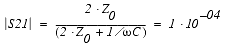
One method is to solve for the minimum resolvable capacitance, given an input power and a dynamic range. This should be done for both S21 (Cbc) and S11 (Cbe), because their respective resolutions are different.
S21 Related to Cbc
S11 Related to Cbe
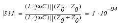
This analysis verifies the observation that Cbc measurements are cleaner than Cbe measurements.
With an Agilent 8515B test set the same capacitance would put the signal 40 dB above the noise floor, which would allow 20 dB of leeway even as low as 100 MHz.
This verifies the initial statement that it is the S-parameter test set that determines the available range of power, and not the synthesized sweeper.