Print version of this Book (PDF file)
Performing Hardware Setup in IC-CAP
The measurement system hardware is controlled by the IC-CAP software. This procedure configures IC-CAP to recognize the system instruments on the GPIB, and the individual source/monitor units (SMUs) in the DC source/monitor. The complete procedure need only be done after initial system installation, or any time the system hardware is changed, to establish a system handshake. The second part of the procedure (renaming the SMUs) also needs to be done any time you change device types, such as from FET to BJT or from BJT to FET.
For help with launching IC-CAP and opening the model file you need, refer to Chapter A, "Agilent 85190A IC-CAP," then continue with these steps:
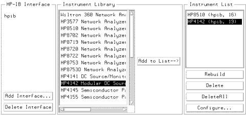
| 1 | In the IC-CAP Main menu bar select Tools > Hardware Setup. The hardware window is displayed. It will vary depending on the system hardware used, but will be similar to the following figure. |
| 2 | Under the Instrument List select Rebuild. This command causes IC-CAP to poll all available GPIB addresses and add to the Instrument List any newly connected instruments that are powered up. (It does not affect instruments already on the list, whether they are powered up or not.) |
Renaming the SMUs
Use this procedure any time you change device types, such as from FET to BJT or from BJT to FET, so that the measurement setups can properly communicate with the bias supplies.
When you run the IC-CAP software, it initially identifies the plug-in SMUs according to the numbers of the Agilent 4142 slots in which they are installed. A medium-power SMU occupies one slot. A high-power SMU occupies two slots, and is identified by the higher slot number of the two. An Agilent 85122 system can include different combinations of SMUs: the standard system used in the example procedures includes two SMUs, one Agilent 41421B medium-power SMU and one Agilent 41420A high-power SMU. The medium-power SMU is factory-installed in slot 1 and is initially identified in the IC-CAP software as MPSMU1. The high-power SMU is installed in slots 2 and 3, initially identified as HPSMU3. The ground unit is identified as GNDU. It is generally more convenient to assign unit names to the SMUs that identify their purpose in a device measurement, depending on the bias connections at the device terminals and the type of device you are modeling.
In configuring IC-CAP to recognize the system hardware, you need to set the SMU names used in software to identify the SMU connections at the measurement terminals. In a FET measurement, the SMUs are identified as VG (gate supply) and VD (drain supply). In a BJT measurement, the SMUs are identified as SMU1 and SMU2, corresponding to the network analyzer test ports: this helps to facilitate measurement of a BJT with only two SMUs, since the port 2 SMU will be used for measurements at both the collector and emitter terminals.
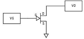
The following figure illustrates the SMU unit names for a FET measurement and the correspondence to the device terminal connections.
Figure 192 SMU Unit Names for a FET Measurement
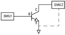
The following figure illustrates the SMU unit names for a BJT measurement and the correspondence to the device terminal connections
Figure 193 SMU Unit Names for a BJT Measurement
| 1 | In the Instrument List click on HP4142 to highlight it. Select Configure and the Configuration of HP4142 window is displayed. |
| 2 | The Unit Table lists the SMUs. Also listed for each is a unit ID (identification) name that can be edited. |
- In a FET measurement, the medium-power MPSMU1 is renamed VG, because it is connected to the gate terminal; and the high-power HPSMU3 is renamed VD, because it is connected to the drain terminal.
- In a BJT measurement, the medium-power MPSMU1 is renamed SMU1 because it is the port 1 SMU; and the high-power HPSMU3 is renamed SMU2 because it is the port 2 SMU.
- In a BJT measurement, the medium-power MPSMU1 is renamed SMU1 because it is the port 1 SMU; and the high-power HPSMU3 is renamed SMU2 because it is the port 2 SMU.
| 3 | To make this change, click left with the mouse and move the mouse pointer over the name assigned to MPSMU1 to highlight it. Then type in the new name, and press Return. Similarly, change MPSMU3's assigned unit name. Then select OK to close the configuration window. |
| 4 | You can close the Unit Table tile by clicking middle again. |
| 5 | To save this hardware configuration in a file for future use, select Hardware, then Write to File. A file filter is displayed, showing the pathname of the current directory. Type in an appropriate name for the .hdw file you are creating, and select OK. |
| 6 | Close the hardware window. |
After IC-CAP is configured to recognize the system hardware, you can proceed to one of the modeling chapters.


