Defining the Instrument States for S-Parameter Measurements
IC-CAP provides remote control of the DC source/monitor and the network analyzer to measure the device under test. These procedures configure IC-CAP with both the DC source/monitor and Agilent 8510 network analyzer instrument states for S-parameter measurements. The first procedure sets the instrument states for a broadband swept-frequency measurement, and the second for a CW frequency measurement.
Instrument States for Swept Measurements
You will need to set the instrument states separately for each measurement setup in a modeling procedure. However, use the same settings for all the swept S-parameter measurement setups in one model (except that Integ Time can differ among setups, as explained under Defining the DC Source/Monitor Instrument State) Unless you use the example settings documented here, write down the settings you use, to duplicate among setups within one model.
This procedure uses the sparm_bias setup in the BJT measurement as an example, though the explanations here apply to all swept-frequency S-parameter measurements in the different device measurement procedures.
|
Note
|
|
|
|
|
Source parameters such as frequency range are not set in this procedure, but in the individual S-parameter setup procedures in each model chapter.
|
|
|
Note
|
|
|
|
|
Do not use these settings for a CW S-parameter measurement. The settings for a CW measurement are different, and are documented later.
|
|
| 1 |
In the DUT/Setup panel select the S-parameter setup you need, for example sparm_0v. |
| 2 |
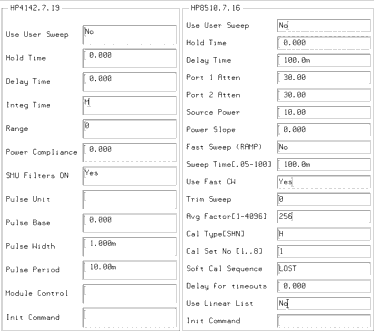
Select the Instrument Options tab, and a window will be displayed showing the instrument states. The following figure illustrates example instrument states. |
Figure 195 Instrument States for Swept Measurements
|

|
| 3 |
Set the Agilent 4142 instrument state the same as for the DC measurements. |
| 4 |
Set the Agilent 8510 instrument state according to the actual hardware configuration, the calibration used, and the device to be measured, following these guidelines: |
| 5 |
Set Use User Sweep to No, to use the instrument's standard internal sweep. This is necessary for the network analyzer's calibration to be switched on. |
| 6 |
Hold Time is the time in seconds before the instrument starts a sweep, to allow for DC settling. Generally, no hold time is required. |
| 7 |
Delay Time is the delay in seconds the instrument waits before setting each frequency in user sweep mode. The default is 100.0m, but the value set will not affect an internal sweep. |
| 8 |
Set Port 1 Atten and Port 2 Atten to the same levels in dB that you set in the network analyzer calibration. While the default is 0 dB, you may need to add attenuation for measurements of amplifiers or high-power devices. |
| 9 |
Source Power is the RF synthesizer output power. Set it to the same value in dB that you set in the network analyzer calibration. |
| 10 |
Power Slope is used only if you use power slope in the network analyzer calibration: if so, set the corresponding value here. This is useful to view the response of a device with power dropoff at higher frequencies. The units for power slope are dB/GHz; the default value is 0.000. (A network analyzer message will caution you that the correction may be invalid, but this can be ignored.) |
| 11 |
Set Fast Sweep (RAMP) to No, because the network analyzer is in stepped-sweep mode, set earlier in the calibration procedure. |
| 12 |
Sweep Time applies only to ramp sweep mode, therefore the value set is irrelevant for a stepped-sweep measurement. |
| 13 |
Set Use Fast CW to Yes, to minimize repeated switching between the test set ports. |
| 14 |
Trim Sweep is set to 0. This feature is used only in ramp sweep mode. |
| 15 |
Set Avg Factor to the same averaging factor you set in the calibration. The default value is 256, but as little as 16 may be adequate. |
| 16 |
Set Cal Type (SHN) to H, for hardware. |
| 17 |
Set Cal Set No to the cal set number in the analyzer where you stored your swept calibration, so that IC-CAP can find the calibration. |
| 18 |
Soft Cal Sequence refers to the sequence of measurements of the cal standard devices: load-open-short-thru. |
| 19 |
Delay for Timeouts can generally be set to the default value of 0.000. |
| 20 |
Set Use Linear List to No because this is a standard stepped-frequency measurement. |
| 21 |
Init Command sets the instrument to a mode not supported by other fields in this table. It is not used in this model. Leave the field blank. |
| 22 |
Close the instrument options window. Then return to the modeling procedure. |
Instrument States for CW Frequency Measurements
The instrument states for a CW S-parameter measurement are similar to those for a swept measurement, with a few important exceptions, listed below.
You will need to set the instrument states separately for each measurement setup in a modeling procedure. However, use the same settings for all the CW S-parameter measurements in one model (except that Integ Time can differ among setups.) Unless you use the default settings documented here, write down the settings you use, to duplicate among setups within one model.
This procedure uses the sparm_cje setup in the BJT measurement as an example, though the explanations here apply to all CW S-parameter measurements in the different device measurement procedures.
|
Note
|
|
|
|
|
Frequencies are set in the setup Inputs, therefore they do not affect instrument states even if you choose to use different CW frequencies for different measurements, except for the Cal Set No where they are stored.
|
|
| 1 |
In the DUT-Setup panel select the CW S-parameter setup you need, for example sparm_cje. |
| 2 |
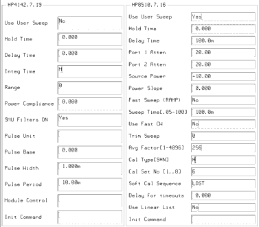
Select the Instrument Options tab, and a window will be displayed showing the instrument states. Figure 196 illustrates example instrument states. |
| 3 |
Set the Agilent 4142 instrument state the same as for the DC measurements. |
| 4 |
Set Use User Sweep to Yes, because CW is a nonstandard sweep. |
| 5 |
(Be sure to set Port 1 Atten and Port 2 Atten and Source Power to the same values as you used in the network analyzer calibration.) |
| 7 |
Set Cal Set No to the cal set number in the analyzer where you stored your CW subset calibration. This must be different from the cal set used by the swept broadband calibration, and from any CW calibration you make at a different frequency for any different measurement. |
Figure 196 Instrument States for CW Frequency Measurements
|

|
| 8 |
If necessary, refer to the Agilent 8510C Operating and Programming Manual for more detail. |
| 9 |
Close the instrument options window. Then return to the modeling procedure. |
|

