Print version of this Book (PDF file)
Extraction of Model Parameters
This section describes the parameter extraction sequence and the extraction strategy.
Parameter Extraction Sequence
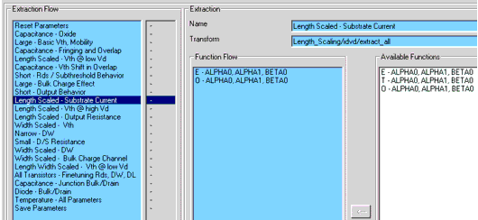
The default setting of the extraction flow is programmed according to a procedure found to give best extraction results. Using this macro, everything is done automatically.
The extraction functions are equipped with error and plausibility checks. If an error occurs or some parameters have strange or unrealistic values, you will get an error warning at the end of the macro.
In some cases, it can be useful not to extract all the parameters. For instance, if a 3.0 micron CMOS process has to be modeled with BSIM3, the typical short channel effects of the threshold voltage are not given and the extraction of the parameters DVT0, DVT1, and so on can result in very unrealistic values. In this case, those parameters should be removed from the extraction flow.
In general, if the macro produces errors, you should add the visual tuning feature to those parameters that caused the error. In a further run, the correspondent curves are simulated and displayed, and the user can try to find the source of the error.
The sequence of the model parameter extraction is shown in the following figure. You can modify this extraction flow by editing the flow if you find another sequence that better fits your special process.
Extraction Strategy
This section describes two aspects of the extraction strategy: a group extraction and a physically oriented model parameter extraction.
Group Extraction Strategy
A major enhancement of the BSIM3v3 model compared to older simulation models is that one set of model parameters covers the whole range of channel lengths and channel widths of a certain process that can be used in circuit designs. Many effects in the BSIM3 model depend very strongly on device dimensions such as the channel length and width. This is considered in the determination of model parameters in the BSIM3v3 Modeling Package through the use of a group extraction strategy.
The following figure shows the principle procedure of model parameter extraction as it was used in older models like the MOS Level 3 model. The model parameter Px is determined from the measured electrical behavior of one single test transistor. The measured data is transformed in such a way that Px can be determined with regression methods.
Figure 144 Model Parameter Extraction from Single Devices
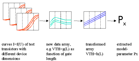
In contrast, the group extraction strategy, which is shown in the following figure, uses the measured electrical behavior of several test transistors with different gate lengths and gate widths.
Figure 145 Group Extraction Strategy
In a first step, intermediate values like the threshold voltage Vth are determined and stored in a new data array as a function of gate length. In the next step, this new data array is transformed in such a way that the model parameters Px can be determined with regression methods. Parameters extracted with this method describes the behavior very well of the devices in a wide range of channel lengths and channel widths.
Physically Oriented Model Parameter Extraction
For the determination of device model parameters from measured I-V or C-V curves, usually two general principles are applied—the optimization of the simulated device behavior or the parameter extraction based on the device equation.
The basis of the optimization process is the simulation of a device with exactly the same inputs (voltages, currents) that are used to measure the device. The error between simulated and measured data is the cost function for the optimization algorithms, which changes certain model parameters of the device, re-simulates it, and checks whether the error has increased or decreased. The advantage of this procedure is that the fitting between the measured curves and the simulated ones can be very good because the optimizer always tries to minimize this difference. However, in order to achieve this very good fitting, the optimization algorithm can give the model parameter physically unreasonable values. Another disadvantage is that many optimization algorithms are not able to find the global minimum of the failure function, which is the difference between measurement and simulation, and the success of the optimization depends on the start values of the model parameters. The last difficulty that can arise by using pure optimization algorithms for the model parameter determination is that the boundaries for the optimization process must be set very carefully. This means that the user of the optimization algorithm must have good knowledge about the device model and where the different model parameters have their influence on the device behavior in order to restrict the optimization process to a certain range of data.
In contrast to the optimization strategy, the extraction strategy is strictly based upon the device equations. If these device equations are physically oriented, as in the case of the BSIM3v3 model for MOS transistors, the extraction of the model parameters must give an accurate and realistic representation of the device physics. The basic idea of this extraction strategy is to transform measured data into such a form that model parameters of a certain part of the device equations can be derived by mathematical regression methods. The extraction routines must therefore incorporate much more knowledge about the model and its behavior. Generally, model parameters extracted in this way are more realistic and physically oriented. However, the fitting between the measured and simulated curves can be less accurate than in the case of an optimization, because the extraction method gives a realistic physical representation of the device while the optimization only targets a minimum error between measurement and simulations.
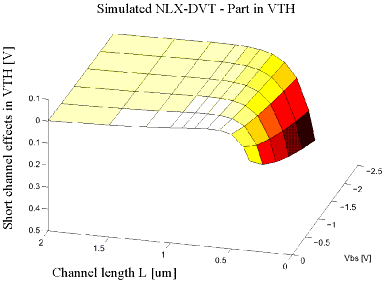
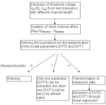
Figure 147 shows the principle data flow of such an extraction routine for the short channel model parameters DVT0 and DVT1. In this example, the threshold voltage Vth of several test transistors with different gate lengths is determined and stored in an intermediate data array. The short channel effect ΔVth is isolated in the next step from Vth as a function of gate length and bulk voltage Vbs. The following figure shows ΔVth as a function of those two variables. Only a subset of this data array is used for the determination of DVT0 and DVT1, and the boundaries for defining this subset are set by the extraction routine. As shown in the flowchart in Figure 147, different results from this action are possible. In the first case, no data point is available for the extraction and the user is informed with a warning message. This may occur for instance after measurement errors or with old CMOS processes that do not show a short channel effect. As a further possible result, only one usable data point is returned. From this data point, one model parameter can be determined while the second one has to be set to its default value.
Figure 146 Short Channel Effects in Vth as a Function of Gate Length and Vbs
In the normal case, a group of usable data points can be identified and transformed in such a way that DVT0 and DVT1 can be extracted through linear regression methods.
Figure 147 Extraction of Short Channel Effect Parameters DVT0, DVT1


