Print version of this Book (PDF file)
Configuring Plot Optimizer Inputs
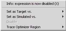
Traces are normally disabled when the plot is first defined. An X before the trace name in a Plot window's Optimizer menu indicates that the trace is disabled. Disabled traces are not used or synchronized with the Plot Optimizer.
Before a trace can be used in the Plot Optimizer, it must be configured as either Target or Simulated based on its definition.
Traces are defined by typing an equation into the Y or X Data fields in the Plot Editor. An equation uses datasets (e.g., inputs, outputs, or transform results), constants, and variables. Similar to a transform, evaluating an equation results in a dataset. Depending on the datasets used to define the equation, the resulting dataset is one of the following four dataset types:
| • | MEAS—includes only measured data |
| • | SIMU—includes only simulated data |
| • | BOTH—includes both measured and simulated data |
| • | COMMON—includes common data |
Usually MEAS, SIMU, and BOTH dataset types are the result of evaluating equations that use outputs. COMMON dataset types can be the result of equations that use input sweeps or a program.
The equation's Y or X Axis Type determines which functions are used to insert the trace equation into the Plot Optimizer.
| • | If a trace equation is defined as Y Data 0 to Y Data 7 and the Y Axis Type is LINEAR, then the equation is inserted without using a function except for the mdata() and sdata() functions which may be used to separate measured and calculated data. |
| • | If a trace equation is defined as Y Data 0 to Y Data 7 and the Y Axis Type is LOG10, then the equation is inserted using the LOG10() function. |
The ABS() function is used to avoid LOG10() or DB() of negative numbers.
Note
| • | If a trace equation is defined as Y Data 0 to Y Data 7 and the Y Axis Type is DB, then the equation is inserted using the DB() function. |
Trace equations defined as Y2 Data follow the same rules depending on how the Y2 Axis Type is defined (LOG10, LINEAR or DB).
Setting the system variable PLOTOPT_USE_YAXES_TYPE to No (the default is Yes) prevents the Plot Optimizer algorithm from using the LOG10() and DB() functions regardless of the Axis Type.
Manually Configuring Optimizer Inputs
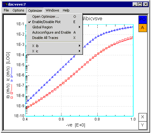
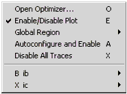
To manually configure the inputs, choose Optimizer then select a trace from the menu. Depending on the trace you select, you will have one or more of the following choices:
| • | Set as Both Target and Simulated |
| • | Set as Target vs. |
| • | Set as Simulated vs. |
If you selected a BOTH dataset type trace, your choice is Set as Both Target and Simulated.
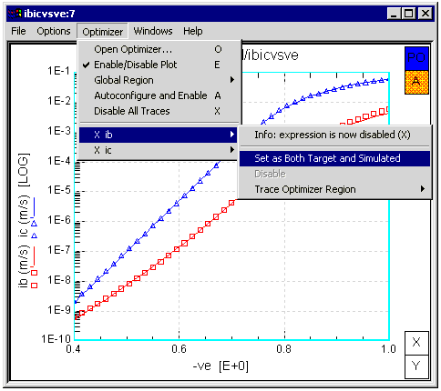
After selecting Set as Both Target and Simulated, a B is displayed before the trace name in the Optimizer menu.
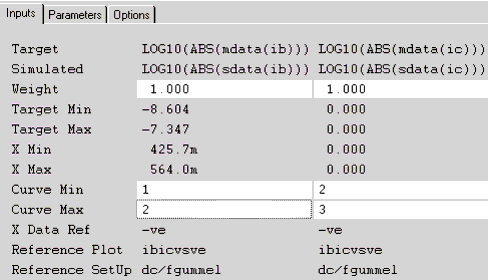
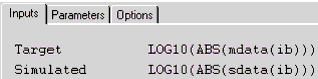
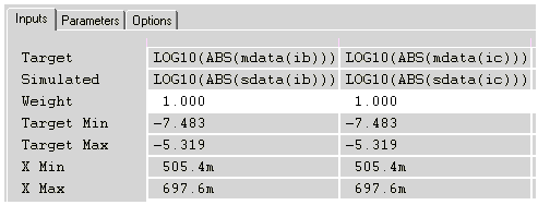
In the Plot Optimizer Inputs table, the trace is configured with its measured data set as Target and its simulated data set as Simulated. The mdata() and sdata() functions fill the Inputs table with the correct data. For example, if the trace ib is set to Both Target and Simulated, the Inputs table is configured as shown in the following illustration:
If you selected a MEAS dataset type trace, your choice is Set as Target vs. After selecting Set as Target vs., select a trace from the resulting drop-down menu. Your choices will be SIMU or COMMON dataset type traces.
If you selected a SIMU dataset type trace, your choice is Set as Simulated vs. After selecting Set as Simulated vs., select a trace from the resulting drop-down menu. Your choices will be MEAS or COMMON dataset type traces.
If you selected a COMMON dataset type trace, your choices are Set as Target vs. or Set as Simulated vs. After selecting Set as Target vs. or Set as Simulated vs., select a trace from the resulting drop-down menu. Your choices will be MEAS or COMMON dataset type traces.
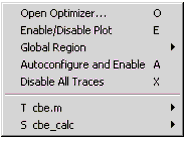
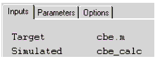
After configuring a trace as Target, a T is displayed before the trace name in the Optimizer menu. After configuring a trace as Simulated, an S is displayed before the trace name in the Optimizer menu.
The Target trace and its associated Simulated trace are inserted together in the Plot Optimizer Inputs table.
Automatically Configuring Optimizer Inputs
To automatically configure the traces in a Plot window, choose Optimizer > Autoconfigure and Enable.
Traces that meet the following criteria are automatically configured:
| • | If a plot has only two traces and one trace's dataset type is MEAS and the other trace's dataset type is SIMU or COMMON, then the MEAS dataset type trace is set as Target versus the other trace regardless whether it was a SIMU or COMMON dataset type. |
| • | If a trace's dataset type is BOTH, then that trace is configured as Both Target and Simulated. |
| • | If a plot has multiple traces and one trace's dataset type is MEAS, then an algorithm searches for an SIMU dataset with the same name. If found, the two traces are paired with the MEAS dataset type trace set as Target versus the SIMU dataset type trace. |
To disable all traces in a Plot window, choose Optimizer > Disable All Traces.
Defining Limits for Target and X-axis Values
You can set limits for all target and X-axis values in a plot by defining a global trace region. You can also set limits for specific target and X-axis values in a plot by defining a trace optimizer region.
Global Region
To define a trace region for all traces in the plot, form a rectangle of the desired trace region then:
| • | Choose Optimizer > Global Region > Reset to delete all existing global trace regions on the plot and define a new global trace region. |
| • | Choose Optimizer > Global Region > Add to add a global trace region without deleting existing global trace regions. |
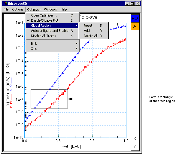
The target and X-axis values for all traces are automatically set to the trace region defined by the rectangle.
To remove all global trace regions, choose Optimizer > Global Region > Delete All.
Trace Optimizer Region
To define a trace region for a specific trace in a plot, form a rectangle of the desired trace region then:
| • | Choose Optimizer, select a trace, then choose Trace Optimizer Region > Reset to delete all existing trace optimizer regions for the selected trace and define a new trace optimizer region. |
| • | Choose Optimizer, select a trace, then choose Trace Optimizer Region > Add to add a trace optimizer region. |
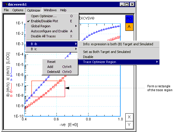
The target and X-axis values for the selected trace are automatically set to the trace optimizer region defined by the rectangle.
To remove all trace regions for a trace, choose Optimizer, select a trace, then choose Trace Optimizer Region > Delete All.
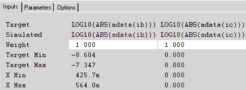
Defining Curve Min, Curve Max, and Weight
You can define Curve Min, Curve Max, and Weight optimizer inputs by completing the Inputs table.
If you disable then re-enable a plot or trace, the values for that plot or trace are reset to their default values.
Note
The following describes the fields that can be edited in the Inputs table:
Weight
Curve Min
Lower limit for the curve. For a family of curves, curves numbered lower than this limit are ignored during optimization. A single curve can be selected by entering the same curve number in both the Curve Min and Curve Max fields.
Curve Max
Upper limit for the curve. For a family of curves, curves numbered higher than this limit are ignored during optimization.