Specifying the Circuit Definition
The circuit definition specifies the parameters to be extracted and the representation of the model in the simulator. The parameter values act as defaults in IC-CAP. In the supplied model files, these values are usually set to SPICE defaults. However, you may want to specify values for the devices or circuits that you plan to characterize, since extractions and optimizations run faster if starting parameter values are closer to the final values. For a complete description of the types of circuits that can be defined, refer to Chapter 6, "Simulating."
Example
The example circuit is a supplied model, nmos2.mdl, that extracts parameters for the Level 2 N-channel UCB MOSFET transistor.
 .OPTIONS ucb
M1 1=D 2=G 3=S 4=B MOSMOD L=2u W=3u AD=9p PD=12u AS=9p PS=12u
.MODEL MOSMOD NMOS
+ LEVEL = 2
+ UO = 600
+ VTO = 0
+ NFS = 0
+ TOX = 100n
+ NSUB = 1e15
+ UCRIT = 10.00K
+ UEXP = 0
+ VMAX = 1MEG
+ RS = 0
+ RD = 0
+ XJ = 0
+ LD = 0
+ DELTA = 0
+ NEFF = 1.00
+ NSS = 0
+ CGSO = 0
+ CGDO = 0
+ CGBO = 0
+ CBD = 0
+ CBS = 0
+ CJ = 0
+ MJ = 0.5
+ CJSW = 0
+ MJSW = 0.33
+ IS = 1.0E-14
+ PB = 0.8
+ FC = 0.5
The circuit definition begins with the Options definition (.OPTION). The definition lists the device to be measured, the device nodes, the name of the model card that contains the model parameters used by the device, and the device parameters. In the example
:
| • |
The first item identifies the device to be measured, M1. The character M indicates that the device is a MOSFET. |
| • |
Next, the device nodes are identified (1 = drain, 2 = gate, 3 = source, 4 = bulk (substrate). |
| • |
The next item, MOSMOD, is the name of the model card that contains the model parameters used by the M1 device. |
| • |
The remaining items in the Options definition specify device parameters. For real devices, refer to the design specification for the values of device parameters. |
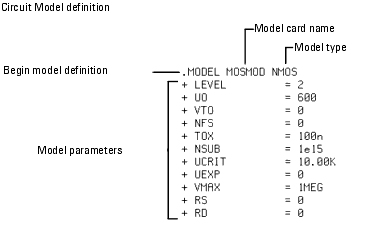
The next section is the model card definition (.MODEL). The definition lists the name of the model card, the model type, and the contents of the model card. The contents of the model card consists of the parameters that are to be extracted (model parameters) and their assigned initial values. In the example
:
| • |
The name of the model card is identified (MOSMOD), then the model type N-channel (NMOS). |
| • |
The remaining lines are the contents of the model card. These consist of the parameters that are to be extracted (model parameters) and their assigned initial values. The leading + indicates that each parameter follows the preceding just as if all the parameters had been entered on a single line. |
To specify the circuit definition:
| 1 |
In the Model window, click Circuit to open the folder. |

| 2 |
Edit the existing values by selecting the value and typing over it. |
| 3 |
When you move the mouse pointer out of the window, the new circuit description is parsed automatically. This parse only occurs after a change has been made to the contents of the circuit description. |
Syntax errors are reported in the IC-CAP/Status window and must be corrected. For example, if the wrong type of simulator is selected and syntax errors result from the parse, you must parse the circuit after the correct simulator is specified.
To parse the circuit definition manually, click Parse.
|
Note
|
|
|
|
|
You can copy the circuit definition from an existing model. Open the model you want to copy. Open the Circuit folder. Select Edit > Copy Circuit. In the new model, select Edit > Paste Circuit.
|
|
Implementing Macro Models
Macro modeling provides a powerful method for defining and simulating new models in IC-CAP. The approach is particularly useful when a complex topology is required. There are several ways to create macromodels. For example, enter the model in the form of a circuit definition and include any model component that is supported by SPICE. Another method is to enter new model equations using the dependent voltage and current sources, although the equations for these sources are limited to polynomial functions.
|


