Print version of this Book (PDF file)
Defining DUT Options
IC-CAP models usually contain several DUTs. DUTs contain groups of setups that have a similar physical connection to the device. Each DUT contains its own DUT parameter set and test circuit. If two setups require differences in either of these areas, you must define a different DUT for each.
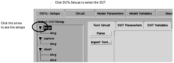
Before you can measure a device, you must make any needed changes to the DUT options. The DUTs-Setups folder displays the DUTs and setups in the model. Three folders are available for defining DUT options.
To view the DUT options and make a device active, select DUTs-Setups. Then select the DUT. If necessary, display the list by clicking the arrow button.
Accelerator Pop-Up Menus
In the DUTs/Setups tree structure, you can view pop-up menus that make it easier for you to perform actions on DUTs and Setups. To view the menus, right-click with your mouse pointer over a DUT or Setup name. The menus for a DUT and a Setup are different. The commands available in the menus enable you to perform selected actions that are allowed for the DUT/Setup. These are the same actions that are available in the Model window's main menu bar and folders. The pop-up menus save time by enabling you to perform an action on a DUT or Setup while avoiding the time required to display the folder contents in the work area.
As you work through this example, try also using these pop-up menus to perform the actions. The contents displayed in the Model window's work area depends on the DUT/Setup folder currently displayed in the work area, and which pop-up menu item you right-click on. When you right-click on a DUT or Setup, it is selected just as if you left-clicked on it. For a DUT or Setup folder displayed in the work area, if you perform an action from the pop-up menu normally associated with a different folder, the associated folder is not displayed in the work area. If a folder is currently shown, and you right-click on a different DUT or Setup, the current folder closes so there is no inconsistency between the selected DUT or Setup and the work area.
Defining a DUT Test Circuit
You can use the Test Circuit folder to attach additional circuitry between the device or circuit being modeled and the measurement hardware. For example, an OpAmp may need to be connected in different configurations for different measurements.
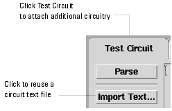
For complete information on defining Test Circuits, refer to Chapter 6, "Simulating."
Note
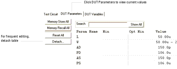
Defining DUT Parameters
You can edit the values of parameters that change from one DUT to another (such as, channel length and width for a MOSFET). In addition, you can set limits by defining minimum and maximum values for each parameter. If a parameter value is outside its limits, it will be clamped to its minimum or maximum value.
After editing the values, you can temporarily store the current set of parameter values (Memory Store All), recall stored parameter values (Memory Recall All), apply the changes to the circuit definition (Update Circuit), reset the default values specified in the circuit definition (Reset All).
To view the DUT parameters, select DUT Parameters.
Defining DUT Variables
The DUT Variables folder contains the names and values of all variables that are global to the DUT.
To view the DUT variables, select DUT Variables.
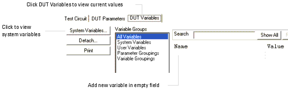
To view system defaults from the DUT Variables folder, select the
Note
![]() button.
button.