Print version of this Book (PDF file)
Configuring the System Hardware
The Agilent 85123A system is shipped from the factory with all rack components and instruments assembled and cabled in the system rack cabinet.
System hardware configuration need be done only in the following circumstances:
| • | At initial system setup. |
| • | If changes are made to the system hardware. |
| • | To change the bias connections for a different device type. |
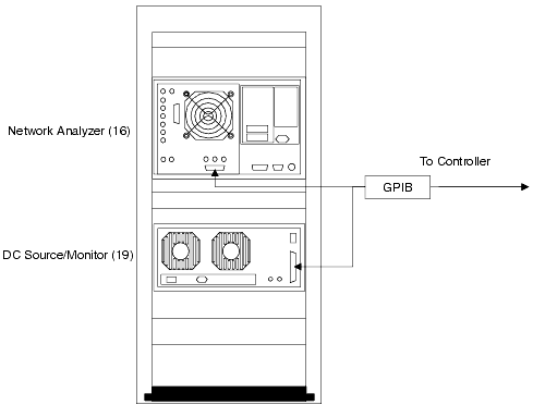
Before starting a parameter extraction procedure, make sure the GPIB cables are connected as shown on the next page, with the GPIB addresses set correctly.
If you are using a special custom system, refer to its installation and user's guide for custom cabling diagrams. The standard and special option Agilent 85123A installation and user's guides also provide additional information you may need about setting up your system components.
Connect the RF cables from the test ports to the RF IN ports of the bias networks, using adapters as needed.
The following provides details of the DC bias connections.
Figure 197 GPIB Interconnections and GPIB Addresses
DC Bias Safety Considerations
Bias current and voltage are supplied to a device under test from the plug-in source/monitor units (SMUs) in the Agilent 4142B DC source/monitor, connected to the device through the bias networks and probes or fixture.
Interlock Connection
To prevent electric shock from DC voltages in excess of +/-42V, do not close the INTLK (interlock) connection of the Agilent 4142B DC source/monitor. The high-power SMU output can be as high as +/-200V, and the medium-power SMU output can be as high as +/-100V. As long as the INTLK connection is open, the DC voltage is clamped at +/-42 VDC.
Floating Ground
IC-CAP measurements are normally performed with the device in a floating-ground configuration, to prevent ground loop noise or, in the case of a BJT, possible damage to a device. A floating-ground configuration is accomplished by insulating the fixture or probe station from power-line ground, for example with an insulator between the wafer under test and the chuck of a probe station. If you are measuring in a floating-ground configuration, make sure the shorting bar of the Agilent 4142B is connected between the CIRCUIT COMMON and CHASSIS GROUND terminals on the front of the GNDU plug-in.
If you cannot implement a floating-ground configuration, it may be necessary to open the Agilent 4142B shorting bar and connect the DUT ground to the circuit common grounds at the DUT ends of the SMU and GNDU cables. The circuit common grounds are not connected through the bias networks: they are available at the input jacks. Refer to the Agilent 4142B Operation Manual chapter 3, "Test Device Connections," and read the section titled "If the Test Device Is Externally Grounded (Floating Measurement)." This provides detailed instructions on making the necessary connections.
Configuring the SMUs and Bias Networks
Bias current and voltage are supplied to a device under test from plug-in source/monitor units (SMUs) in the Agilent 4142 DC source/monitor, connected to the device through the bias networks and probes or fixture. The standard Agilent 85123A system includes one medium-power SMU and one high-power SMU.
The quadraxial cables from the SMUs are routed through a cable feedthrough panel to the rear of the system rack, and out to the front of the rack above the work surface through another feedthrough panel.
Connect the cables emerging from the upper feedthrough panel to the bias networks, as explained in the next paragraphs.
Bias Connections
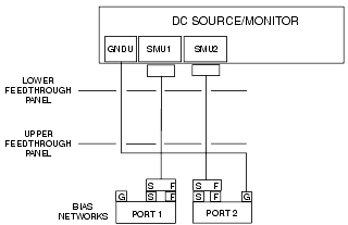
The following figure illustrates the connections from the SMUs to the bias networks. Connect the FORCE and SENSE connectors on the quadraxial cables to the FORCE and SENSE connectors on the bias networks. Connect the triaxial cable from the GNDU SMU to the ground connector on one of the bias networks (usually port 2). Leave the ground connector of the other bias network unconnected.
Figure 198 Connections from DC Source/Monitor to Bias Networks
Connections from Bias Networks to Device
For in-fixture measurements, the measurement procedures in this manual apply to a FET mounted in the fixture in a common-source configuration, or a BJT mounted in a common-emitter configuration.
Note
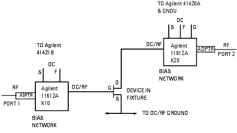
Connect the DC/RF signals from the outputs of the bias networks via the semi-rigid cables to the corresponding terminals of the fixture or probe station. Set up the angle of the cables and bias networks to minimize stress and torque, and ensure that the cables are properly supported. Iterate the positioning of the cables and bias networks until the connectors line up correctly. Use a torque wrench to tighten the connections.
The following figure illustrates the connections for a FET. The connections for a BJT are comparable, with the port 1 DC/RF signal connected to the base, the port 2 DC/RF signal connected to the collector, and the emitter grounded.
Figure 199 Connections from Bias Networks to In-Fixture DUT
| • | For additional hardware information, refer also to the installation and user's guide for your Agilent 85123A RF parameter extraction test system, and to the manuals for the individual instruments in the system. |
| • | For information on fixtures or probe stations, refer to the manufacturer's documentation. |
Switching on Power to the System
Be sure to switch on the network analyzer and the DC source/monitor before the computer, so that the computer recognizes the network analyzer subsystem and the DC source/monitor.


