Print version of this Book (PDF file)
Hierarchical Modeling
The previous test circuit section on illustrated one way to include hierarchy in an overall circuit description. The test circuit, however, is at the highest level of hierarchy in an IC-CAP circuit. It is also possible to build a complete circuit by combining smaller circuit or transistor models into one subcircuit definition. This way, you can update the models of smaller subcircuits or individual components and have these changes automatically propagate into all circuits that use it.
Circuits Built from Sub-models
The ECL logic gate defined in Figure 218 uses two sizes of NPN transistors. Each transistor has a separate .MODEL card associated with it. These transistor model definitions can be removed from the logic gate circuit and reference other models currently active in IC-CAP. When a simulation is performed, IC-CAP includes these device models in the circuit definition.
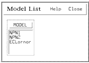
To use external models, the models that you want to include must be in the IC-CAP model list. In the circuit definition that uses these model references, remove the .MODEL card. The model name used for the transistors should then be the same as the names in the IC-CAP model list. To use this technique for the ECL logic gate, read in models for the NPN1 and NPN2 transistors into IC-CAP. Then delete the two model cards in the logic gate circuit. The resulting model list and circuit description are shown in the following 2 figures.
This approach provides flexibility. It allows you to keep a standard library of device models to include in larger circuits requiring accurate device models. This allows you to quickly cut-and-paste different component models into circuits and compare performance. It also greatly reduces the size of the circuit definition that needs to be maintained.
Figure 220 Model List Window for Hierarchical Circuit Definition
