Print version of this Book (PDF file)
Circuit Measurement
The process of measuring a circuit in IC-CAP is identical to measuring a single device. The circuit stimuli and responses are specified in the input and output tables, respectively, of the Measure/Simulate folder. You can perform a measurement by clicking Measure in the Measure/Simulate folder the DUT or Setup levels. In performing measurements on circuits, there are several additional items not found in single component measurement.
Multiple Instrument Names
In measuring a single component, it is common to use only one DC source and measurement instrument because only four terminals are involved. The typical circuit can have more than four terminals and require several DC source and measurement instruments. Any number of instruments of the same or similar type can be connected to the circuit under test as long as they are entered in Hardware Setup. When using multiple instruments, each of their units must have a unique name.
Isolating Circuit Elements for Measurement and Extraction
The characterization of a circuit may require the measurement and modeling of several sub-circuit elements. The accuracy of the sub-circuit model generated is dependent upon how well that circuitry can be isolated from the rest of the overall circuit.
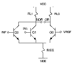
Examine the simplified schematic of the input to an ECL OR/NOR gate in the following figure. The input stage of this circuit is a differential amplifier with a collector resistor in each leg and a resistor for a current source. It is possible to characterize the individual transistors in this circuit by selectively biasing only the terminals that make it active and that keep other parts of the circuit in an off or latent state. In this case, biasing IN1, VCC, and VEE turns on the circuit that contains RL1, Q1, and RIEE. These components have now been isolated so that their model parameters can be extracted. This type of selective measurement allows characterization of individual or small groups of sub-circuit elements.
