Print version of this Book (PDF file)
Measure Window
The Measure window consists of the following six tabbed folders:
| • | Instrument Settings |
| • | Measurement Settings |
| • | Pad Open/Short |
| • | Measure DC |
| • | Measure RF |
| • | Options |
Instrument Settings
Before you start measurements, you need to do some setup. Settings in this folder are Global Settings that can be referred from each measurement setups described later.
Follow the instruction shown on the left of the folder.
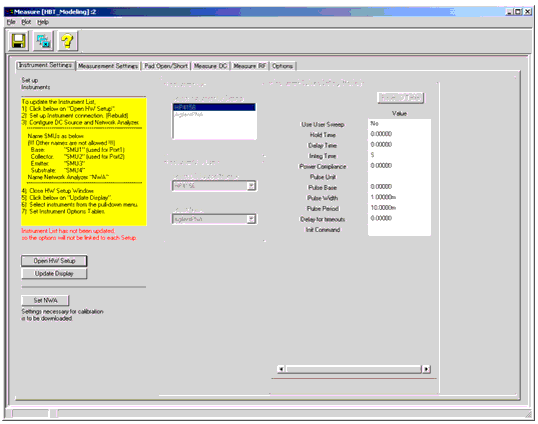
Figure 168 Instrument Settings folder of Measure window
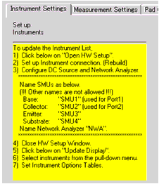
Figure 169 Instruction to set up instruments
Open HW Setup button opens the IC-CAP/Hardware Setup window. The Instrument List in this toolkit folder is cleared when this button is clicked.
Update Display button synchronizes the Instrument List in this toolkit folder according to that in IC-CAP/Hardware Setup window. The right half of the folder is initially de-activated and will be activated when the instrument list is properly updated by clicking this button.
Reset IO Table button refreshes the IO Table entries and resets the values to default, which is set inside the mdl file.
Set NWA button sends settings necessary for calibration to the connected NWA. Before clicking this button, you must set IO Table settings and frequency sweep settings (see Measurement Settings). This button is also on the Measurement Settings folder.
Connect instruments first. Please refer to "Making Measurements" in the IC-CAP User's Manual.
The toolkit supports only dc sources (or dc parameter analyzers) and network analyzers that IC-CAP supports.
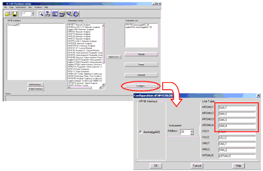
The SMU names must be configured by SMU1, SMU2, (SMU3, SMU4, if necessary) to have the toolkit work properly. These names are required to be set in the IC-CAP/Hardware Setup window before editing any IO Tables in the toolkit.
The network analyzer name must be configured by NWA, otherwise the toolkit will not work properly.
If you get instrument option errors, check the SMU name configuration first. If the errors are still appearing after correctly setting up the SMU names, the Reset IO Table button may resolve the problem.
Note
Set frequency sweep in the next Measurement Settings folder before clicking on Set NWA button.
The instrument options set in this folder are used as master (default) settings in each measurement setup. Integ Time, Hold Time, Delay Time, and Cal Set/State can be individually set later at each measurement in the toolkit's measurement folders (Measure DC folder and Measure RF folder).
For more information on instrument options, see "Supported Instruments" in the Reference manual.
Figure 170 IC-CAP/Hardware Setup window and example of SMU name configuration
Measurement Settings
Temperatures, SMU compliances, and frequency sweep are set here as pre-set values. Settings in this folder are Global Settings that can be recalled in the following measurement folders by clicking on the Recall Setting buttons in each folder.
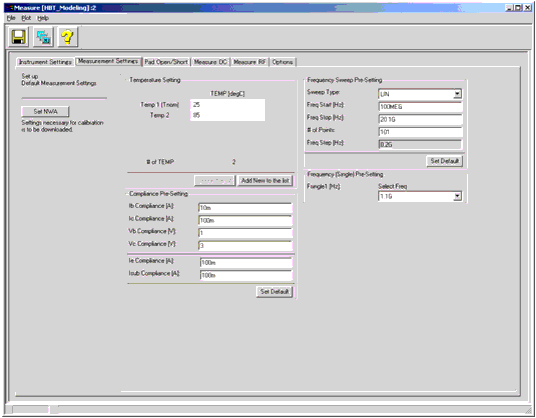
Figure 171 Measurement Settings folder of Measure window
Set NWA button sends settings necessary for calibration to the connected NWA.
Add New to the list button adds one item at the bottom of the list.
Shrink the list button removes one item from the bottom of the list.
Set Default button sets default values defined inside the mdl file.
Temp1 is reserved for Tnom (room temperature).
Temp2 is usually used for High temperature, and Temp3 for Low temperature, if you have add one temperature. The minimum number of the TEMPs is 2.
Note
Pad Open/Short
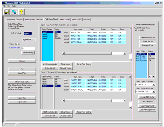
Measurements of pad OPEN/SHORT are performed in this folder.
To make measurements of pads, select a Setup of Open or Short, set frequency sweep, make sure the Cal Set/State is correct, then click on the Measure button. You can recall the pre-setting (global setting) by clicking on the Recall Setting button for Cal Set/State and Recall Freq Setting button for frequency sweep. Data Names are user-definable.
Figure 172 Pad Open/Short folder of Measure window
After Open and Short TEG measurements, De-embedding Set (DSet) need to be defined on the right side of the folder. DSet names are user-definable (click Rename DSet button to change the name). Select Open TEG data and Short TEG data from the pull-down menus, then click on Assign TEG Data button to pair the data sets so that you can use the assigned DSet data for de-embedding in the Measure RF folder. Combination of Open/Short TEG data selection is arbitrarily.
Add New to the list button adds one item at the bottom of the list.
Shrink the list button removes one item from the bottom of the list.
Clear Status button clears measurement status of the selected Setup.
Clear All Status button clears measurement status of all Setups.
Recall Freq Setting button recalls the global frequency setting specified in Measurement Settings folder.
Clear/Reset Data button creates ideal open/short data (by using simulation) in order to be used for Open Only de-embedding or No De-embedding.
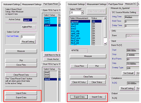
Import Data button and Export Data button are used for data management. When importing data, you can select one of the followings:
| • | Import from opened mdl file (*.mdl file is IC-CAP model file. The mdl file has to be loaded in IC-CAP/Main window before importing.) |
| • | Import from saved mdm data file (*.mdm file is IC-CAP data file.) |
The default exporting data file name is set based on the following rule:
Please refer to Exporting/Importing Measured Data for more information on data management.
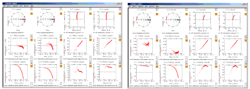
Plot button opens S-parameters plot as shown in the following figure:
Figure 173 Display of Pad Open/Short S-parameters
Pad Parasitics Calculation
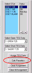
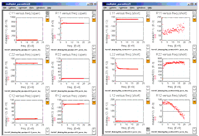
Pad parasitic parameters are calculated by clicking on Calc Parasitics button on the right of the folder after defining the de-embedding set. These parasitics are calculated by assuming a general PI-type or Tee-type equivalent circuit.
Figure 174 Pad parasitics (C, L, R) calculated from measured S-parameters by assuming PI-type or Tee-type equivalent circuit
Measure DC
DC measurements are performed in this folder.
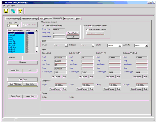
To make DC measurements, select a TEMP, select a measurement setup, set measurement bias conditions, then click on the Measure button to make the measurement. Instrument options, inputs, and compliances can be set at each TEMP. Pre-set values of instrument options and compliances can be recalled by clicking on each Recall Setting button.
Figure 175 Measure DC folder of Measure window
DC Measurement Setup Descriptions
fgummel: Forward Gummel measurement. Vb is swept with Vc synchronized.
rgummel: Reverse (inverse) Gummel measurement. Vc is swept with Vb constant 0.
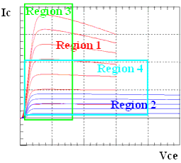
icvc1: Common-emitter Ic versus Vce measurement with forced Ib in Region 1 (see following figure: High-Current Low-Voltage region).
icvc2: Common-emitter Ic versus Vce measurement with forced Ib in Region 2 (see following figure: Low-Current High-Voltage region).
icvc_vbe: Common-emitter Ic versus Vce measurement with forced Vb.
spdc_icib: Ic versus Ib measurement with a constant Vc = Target Voltage. This setup is used to find bias conditions that obtain desired collector current for S-parameter measurements.
ftic1_icib: Ic versus Ib measurement with some Vc in Region 1. This setup is used to determine bias points in Region 1 at which fT will be measured in ftic1 Setup.
ftvc2_icvc: Ic versus Vce measurement with some Ib in Region 2. This setup is used to determine bias points in Region 2 at which fT will be measured in ftvc2 Setup.
ftic3_icib: Ic versus Ib measurement with some Vc in Region 3 (see following figure: region that includes high-current effects, such as Kirk effect). This setup is used to determine bias points in Region 3 at which fT will be measured in ftic3 Setup.
ftic4_icib: [Optional] Ic versus Ib measurement with some Vc in Region 4 (see following figure: Medium-Current Medium-Voltage region). This setup is used to determine bias points in Region 4 at which fT will be measured in ftic4 Setup.
Figure 176 Division of I-V bias plane
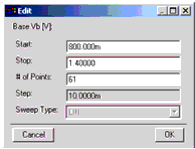
Edit button opens a dialog box for measurement condition settings. Specifying Start, Stop, and # of Points will automatically calculate Step size. Please try to find a combination of these values that make the fraction part of Step size as simple as possible.
Set Default button sets default values defined inside the mdl file.
Recall Setting button recalls the global settings specified in Instrument Settings folder or Measurement Settings folder.
Check data with plot(s) after each measurement to make sure the data are adequate for the parameter extraction.
Change of Probing Style
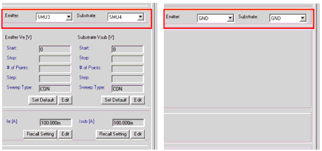
If you would like to perform a 2-port DC measurement without contacting Emitter and Substrate (i.e., using GSG probing), select GND from the pull-down menus as shown below so that you can de-activate the 2 inputs.
Figure 178 Activate/Deactivate the inputs
Measurements at Different Temperatures
To make measurements at different TEMPs, select the TEMP from the pull-down menu on top left of the folder. The temperature values are set in the Measurement Settings folder and the TEMP list in the pull-down menu is automatically updated.
Copy Tnom Setting button copies settings of instrument options (except for Cal Set/State in RF measurements), inputs, and compliances at Tnom to each of those at the selected TEMP.
Figure 179 Change of Temperatures
Auto DUTs/Setups Data Tree Management
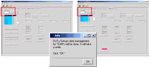
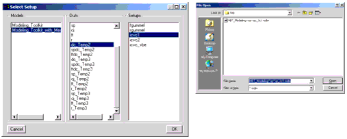
If you changed the number of temperatures in the Measurement Settings folder, the Measure DC folder and Measure RF folder will be deactivated as shown below. By selecting a TEMP from the pull-down menu on the top left of each folder, a dialog informs you that the DUTs/Setups data tree (structure of data in IC-CAP model window) will be processed. This data management process is automatic, but takes a while. Click OK in the dialog box. After finishing the data management, the folder will be activated again.
Figure 180 Auto DUTs/Setups Data Tree Management
Measure RF
RF measurements and de-embeddings are performed in this folder.
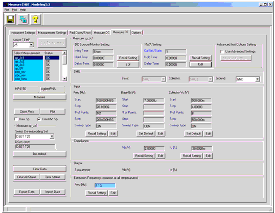
To make RF measurements, select a TEMP, select a measurement setup, set measurement bias conditions, then click on Measure button to make the measurement. Instrument options, inputs, and compliances can be set at each TEMP. Pre-set values of instrument options, frequency sweep, and compliances can be recalled by clicking on each Recall Setting button.
Figure 181 Measure RF folder of Measure window
RF Measurement Setup Descriptions
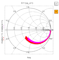
sp_Jc1: Frequency-swept bias-dependent S-parameter measurement in low current region. Ib is constant with Vc being swept to desired voltage.
sp_Jc2: Frequency-swept bias-dependent S-parameter measurement in medium current region. Ib is constant with Vc being swept to desired voltage.
sp_Jc3: Frequency-swept bias-dependent S-parameter measurement in high current region. Ib is constant with Vc being swept to desired voltage.
sp_0V: Frequency-swept S-parameter measurement in zero bias condition. This setup is used to obtain Cbe/Cbc/Cce versus frequency plot.
cbe_rev: One point frequency S-parameter measurement in the reverse bias region for B-E junction. This setup is used to obtain depletion capacitance Cbe versus Vb plot.
cbc_rev: One point frequency S-parameter measurement in the reverse bias region for B-C junction. This setup is used to obtain depletion capacitance Cbc versus Vc plot.
cbe_forw: One point frequency S-parameter measurement in the vicinity of the forward bias region for B-E junction. This setup is used to obtain depletion plus diffusion capacitance Cbe versus Vb plot.
cbc_forw: One point frequency S-parameter measurement in the vicinity of the forward bias region for B-C junction. This setup is used to obtain depletion plus diffusion capacitance Cbc versus Vc plot.
ftic1: One point frequency S-parameter measurement to obtain fT versus Ic at the bias points in Region 1. The bias conditions are set in the corresponding DC Setup and the conditions should be copied to this setup.
ftvc2: One point frequency S-parameter measurement to obtain fT versus Vc at the bias points in Region 2. The bias conditions are set in the corresponding DC Setup and the conditions should be copied to this setup.
ftic3: One point frequency S-parameter measurement to obtain fT versus Ic at the bias points in Region 3. The bias conditions are set in the corresponding DC Setup and the conditions should be copied to this setup.
ftic4: [Optional] One point frequency S-parameter measurement to obtain fT versus Ic at the bias points in Region 4. The bias conditions are set in the corresponding DC Setup and the conditions should be copied to this setup.
sp_re: One point frequency S-parameter measurement to extract emitter resistance using Z12 technique. Ib is swept while Ic is controlled to be zero to make the current flow into emitter.
sp_rc: Frequency-swept S-parameter measurement at some bias points to extract collector resistance.
sp_rb: Fettering-swept S-parameter measurement at some bias points to extract base resistance.
fT Measurements and the Corresponding DC Measurements
Figure 182 Recall DC Setting button of ft setup
If a ft* setup is selected, Recall DC Setting buttons are shown in Input area instead of Set Default buttons. Using these buttons, you can recall bias conditions previously set in the corresponding DC Setups.
Check data with plot(s) after each measurement to make sure the data are adequate for the parameter extraction.
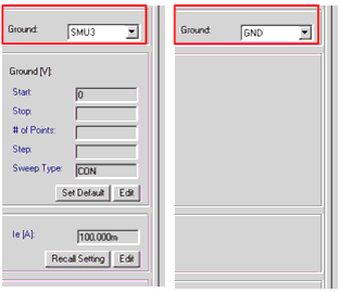
If you would like to use a SMU for ground connection in RF measurement, select SMU3 from the pull-down menu as shown below. If you use GNDU of the dc source, then select GND.
Figure 183 Ground Connection in RF Measurement
De-embedding
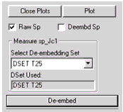
To de-embed pad parasitics, select a de-embedding set from the pull-down menu on the left of the folder, then click on the De-embed button to perform de-embedding. The name of the de-embedding set will be shown in the DSet Used field after finishing the de-embedding.
Figure 184 De-embedding Control Panel
Displaying Raw/De-embedded S-parameters
You can display raw S-parameters or de-embedded S-parameters by selecting the two check boxes on the left of the folder. If you select both, the two kinds of S-parameters are shown in a plot. Other data, such as bias-dependent capacitances, are calculated from either of the two S-parameters according to the selection of the check boxes. If the selection is both, the data are calculated using raw S-parameters.
Figure 185 Showing both raw and de-embedded S-parameters
The data name s represents raw S-parameters and sd represents de-embedded S-parameters.
Before moving on to the next measurement setup in the Measure RF folder, select an Extraction Frequency at the bottom of the folder. The frequency will be used in the extraction part for calculation.
Options for Measurements
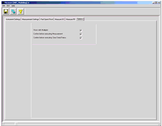
Figure 186 Options folder of Measure window
If Show with Multiplot is checked, the plots will be opened in a Multiplot window. Otherwise the plots will be opened in individual windows.
If Confirm before executing Measurement is checked, you will be prompted with a dialog box before executing measurements. This option is ON (i.e., checked) when starting the toolkit by double-clicking the icon in IC-CAP/Main window.
If Confirm before executing Clear Data/Status is checked, you will be prompted with a dialog box before clearing data/status. This option is ON (i.e., checked) when starting the toolkit by double-clicking the icon in IC-CAP/Main window.
Exporting/Importing Measured Data
In Pad Open/Short, Measure DC, and Measure RF folders, you can export/import measured data to/from MDM data files. The file will be exported to IC-CAP's current working directory as default. When importing data, you can also import data from opened model files that contain corresponding measured data sets.
Descriptions for this data management functionality are as below:
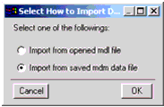
Import Data button and Export Data button are used for data management. When importing data, you can select one from the followings:
| • | Import from opened mdl file (*.mdl file is IC-CAP model file. The mdl file has to be loaded in IC-CAP/Main window before importing.) |
| • | Import from saved mdm data file (*.mdm file is IC-CAP data file.) |
The default exporting data file name is set based on the following rule:
Figure 187 Data Importing/Exporting buttons
Figure 188 Selection of how to import data
Figure 189 28 Selection of data in Import from opened mdl file/Import from saved mdm data file
Requirements/Limitations for Data Import
The data importing functionality has the following requirements/limitations:
| • | The numbers of Inputs and Outputs in the importing measured data must be the same respectively as those in the toolkit's setup to which the data are going to be imported. |
| • | The names of Inputs/Outputs of the data must be vb, vc, ve, or vsub (for 4 nodes) for DC voltages; ib, ic (without ie and isub) for DC currents; freq for RF frequency; and s for RF S-parameters. |
| • | Mode, Sweep Type, and Sweep Order of the Inputs/Outputs of the data must be the same respectively as those in the toolkit's setup. |
| • | Ratio and Offset in SYNC type components must be 1.0 and 0.0 respectively. |
| • | Value of ve or vsub with the unit of GND must be 0.0. |
If the IC-CAP variable of RETAIN_DATA = yes or 1, measured data will be retained when you add/remove an input/output that does not affect the data points structure. If RETAIN_DATA = no or 0, then the measured data in the setup are CLEARED. This is the nature of IC-CAP data management.
Note
