Print version of this Book (PDF file)
HiSIM_HV model
Commonly, two types of structures for high voltage MOSFET's are used: The laterally diffused asymmetric structure usually called LDMOS and the symmetric structure referred to as HV structure.
The HiSIM_HV model is valid for both structures, it is an extension to the HiSIM2 model developed by the University of Hiroshima together with the STARC cosortium. STARC stands for Semiconductor Technology Academic Research Center, co-funded by major Japanese semiconductor companies in 1995.
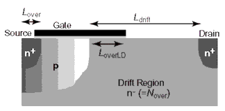
The main differences between a conventional MOSFET and a high voltage one arises from the drift region introduced to enhance the sustainability to high voltages, which is shown in the following cross section of a HV MOSFET.
Accurate modeling of the drift region is the major task in HV MOSFET modeling. This region not only affects the resistance, through additional charges inside the drift region, but the capacitances are affected as well.
The basic equations of the HiSIM2 model are used for HiSIM_HV too, complete with additional equations to model the drift region influence.
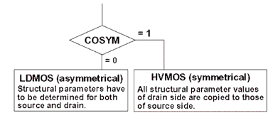
The HV model can be used for simulations of symmetrical as well as asymmetrical device structure. A flag is introduced to switch from the symmetric to the asymmetric device structure. COSYM=0 refers to the asymmetric LDMOS structure, COSYM=1 to the symmetric HVMOS structure. The following figure shows the parameter extraction approach using the COSYM parameter.
HiSIM_HV solves the Poisson equation iteratively, including the highly resistive drift region effects, depending on the structure of the MOS transistor to be modeled.
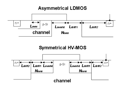
The cross section (Figure 47) through a LDMOS and a HVMOS structure shows the drift region resistance parameters and their usage.
Figure 47 Cross sections and drift resistance parameters
There is a limit for the bulk voltage considered to model the bias dependency of the drift region resistance. This limit is set per default to Vbs,min = -10.5V. However, there is a parameter that can be used to override this default setting, called VBSMIN.
Resistance modeling in HiSIM_HV
The most critical part of modeling a high voltage MOS transistor is the drift region resistance modeling. Therefore, this part needs attention.
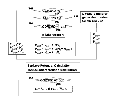
A flag is used to switch between different resistance settings, CORSRD. This flag can have the following values that affect resistance modeling of RS and RD, as is shown in the following table.
The CORSRD flag provides a few more options as shown below.
Figure 48 Options selected by CORSRD
Use care when using the CORSRD flag since more parameters are taken into account depending on the CORSRD flag value. There is the possibility that some parameters may not be considered if others are set to zero. For instance, the equation to calculate the parameter RDVD uses a multiplication of parameters (among others) as shown here:
As you can see, if either LDRIFT1 and RDICT1 or LDRIFT2 and RDICT2 are zero, the whole expression is zero.
The following table gives an overview of the different parameters used with each possible CORSRD flag.
As you can see, the flag CORSRD = 3 is the most comprehensive using the most model parameters.
In most cases, you should use the CORSRD flag with the value 3, which is the default setting in HiSIM_HV.


