Example: Creating a New Model
The example in this section describes the procedure for defining a portion of the MOSFET model. The MOSFET model supplied with IC-CAP contains a variety of DUTs and Setups for characterizing the DC and Capacitance behavior of the device over a range of geometries. The model is described in Chapter 6, "UCB MOS Level 2 and 3 Characterization," in the Nonlinear Device Models, Volume 1 manual. Several alterations have been made to the supplied model in order to illustrate advanced features, such as user-defined variables and test circuitry.
|
Note
|
|
|
|
|
These instructions assume that the necessary source and measuring instruments are already configured to the IC-CAP system. If this is not the case, refer to the Installation Guide.
|
|
Add a New Model to the Work Area
| 1 |
In the IC-CAP/Main window, select File > New. An icon representing a new untitled model appears in the IC-CAP/Main window. |
| 2 |
Double-click the model icon to open the Model window. |
Save the Model File
| 2 |
In the dialog box, enter the design name, nmos2, and choose OK. |
Define Model Variables
| 1 |
In the Model window, select Model Variables. |
| 2 |
Click the first empty row in the Name field and type the variable name, Compliance. |
| 3 |
Press Tab to move to the Value field. Type the variable value, 20m. |
Specify the Circuit Definition
| 1 |
In the Model window, select Circuit. |
| 2 |
Enter the circuit description. For the nmos2 model, the circuit is: |
 .OPTIONS ucb
M1 1=D 2=G 3=S 4=B MOSMOD L=2u W=3u
+ AD=9p PD=12u AS=9p PS=12u
.MODEL MOSCAP NMOS
+ LEVEL = 2.000
+ UO = 600
+ VTO = 0
+ NFS = 0
+ TOX = 100n
+ NSUB = 1E15
+ UCRIT = 10.0K
+ UEXP = 0
+ VMAX = 0
+ RS = 0
+ RD = 0
+ XJ = 0
+ LD = 0
+ DELTA = 0
+ NEFF = 1.00
+ NSS = 0
+ CGSO = 0
+ CGDO = 0
+ CGBO = 0
+ CBD = 0
+ CBS = 0
+ CJ = 0
+ MJ = 0.5
+ CJSW = 0
+ MJSW = 0.33
+ IS = 1.0e-14
+ PB = 0.8
+ FC = 0.5
- The new circuit definition is parsed automatically when you click outside the window.
View Model Parameters
When a new model is read, parameter values are set to the defaults defined in the MODEL definition of the Circuit. To view the model parameters, select the Model Parameters folder. For this example, no changes are made to the model parameters.
Add a DUT
The MOSFET model contains three DUTs for DC characterization and two DUTs for Capacitance characterization. The procedure creates the DC DUT large.
| 1 |
In the Model window, select DUTs-Setups. |
| 3 |
In the dialog box, click Add New DUT. |
| 4 |
In the Enter New Dut Name field, type the DUT name, large. |
View DUT Variables
To view the model parameters, select the DUT name large, then select the DUT Variables folder. For this example, no changes are made to the DUT Variables.
Specify DUT Parameters
The DC characterization of the MOSFET requires measurements on three DUTs. Each of these DUTs have different specifications for L and W. For the example, specify geometry parameters for the large device.
| 2 |
Select the Param Name Value field and edit the DUT parameters for the device being measured. The DUT parameters are: |
-
L - 50.00u
W - 50.00u
AD - 150.0p
PD - 106.0u
AS - 150.0p
PS - 106.0u
Specify a Test Circuit
A test circuit is usually not used with a MOSFET, but this example defines one. You can use a test circuit if you have a large amount of probe resistance that you do not want included in the model parameters. In this case, you can define a test circuit that has an additional resistor connected between each of the internal device nodes and the external nodes that are connected to the sources.
The example test circuit definition contains the following information:
| • |
Line 1 contains the mandatory term .SUBCKT, which is required if a circuit contains more than one device (in this case, a transistor and four resistors). Line 1 also includes the arbitrary name of the test circuit and the identities of the four device nodes. The four device nodes are numbered as in the Model Circuit Definition (1 = C, 2 = B, 3 = E, 4 = S); however, alternate names can be used. If you do not assign a name to each node number, the system assigns the node number as the node name. |
| • |
Line 2 identifies the device (Q1), the internal nodes of the transistor (11, 12, 13, and 14), the name of the model (npn), and the AREA parameter. The model name must be entered precisely as it appears in the model icon. |
| • |
Lines 3 through 6 specify the four resistors that represent the additional resistance at each node. Each resistor is connected from an external Test Circuit node to the corresponding internal device node. |
| • |
Line 7 indicates the end of the .SUBCKT definition. |
To define a test circuit:
| 1 |
In the DUT window, select Test Circuit. |
| 2 |
In the test circuit window, type the test circuit data: |
-
.SUBCKT large 1=D 2=G 3=S 4=B
M1 11 12 13 14 nmos2 L=50u W=50u
RDX 11 1 5.0
RGX 12 2 5.0
RSX 13 3 5.0
RBX 14 4 5.0
.ENDS
When a Test Circuit is defined for a DUT, the parameters in the Test Circuit appear in the DUT parameters folder and are editable.
Add a Setup
| 1 |
In the Model window, select DUTs-Setups. |
| 3 |
In the dialog box, click Add New Setup to Dut large. |
| 4 |
In the Enter New Setup Name field, type the setup name, idvg. |
Specify Setup Components
To perform the measurement and simulation, four input voltages and one output current are specified. In the case of the idvg setup for the large DUT of the MOSFET, the drain current, id, of the device, is monitored as a function of the gate voltage, vg, and the substrate (bulk) voltage, vb. The drain voltage, vd, and the source voltage, vs, are held constant.
For each of the components added to the setup, fill in a table of information that defines the desired behavior. This example presents only a small subset of the available capabilities possible in a setup. To edit a setup:
| 1 |
In the DUT-Setups window, select large/idvg. |
| 2 |
Select Setup Variables and define any variables you want to apply to the setup. |
| 3 |
Select Measure/Simulate. |
| 4 |
Click New Input to open the Input Editor. |
| 5 |
In the Input field, enter the new input name, vg. |
| 6 |
Complete the value entries as shown below: |
|
|
+ Node
|
G
|
- Node
|
GROUND
|
Unit
|
SMU2
|
Compliance
|
10.00u
|
Sweep Type
|
Linear
|
Sweep Order
|
1
|
Start
|
0.000
|
Stop
|
5.000
|
# of Points
|
21
|
Step Size
|
250.0m
|
- The value in the Compliance field is a reference to the global compliance variable that was defined for the setup variables.
| 7 |
Click OK to add the input to the Measure/Simulate folder. |
| 8 |
Add the input vb. Complete the value entries as shown below: |
|
|
+ Node
|
B
|
- Node
|
GROUND
|
Unit
|
SMU4
|
Compliance
|
1.000m
|
Sweep Type
|
Linear
|
Sweep Order
|
2
|
Start
|
0.000
|
Stop
|
-3.000
|
# of Points
|
3
|
Step Size
|
-1.500
|
- The value in the Compliance field is a reference to the global compliance variable that was defined for the setup variables.
| 9 |
Add the inputs that remain constant, vd and vs, by completing the value entries as shown below: |
|
|
|
Mode
|
V
|
V
|
+ Node
|
D
|
S
|
- Node
|
GROUND
|
GROUND
|
Unit
|
SMU1
|
SMU3
|
Compliance
|
100.0m
|
100.0m
|
Sweep Type
|
CON
|
CON
|
Value
|
100.0m
|
0.000
|
- When you change the Sweep Type from LIN to CON the fields at the bottom of the table used to specify a linear sweep are replaced by a single Value field. Similarly, a change in the Mode alters the structure of the upper portion of the table.
| 10 |
Add the output id by completing the value entries as shown below: |
Mode
|
I
|
To Node
|
D
|
From Node
|
GROUND
|
Unit
|
SMU1
|
Type
|
B
|
- When you change the Mode to I, the names of the node fields of the table change accordingly.
Add Transforms
When the measurement has been made, values for the model parameters that control the large DUT behavior are extracted, and, optionally, the parameter values are optimized to achieve the best possible fit between measured and simulated data.
To accomplish this, you add a transform that performs the extraction and a transform that performs the optimization.
| 1 |
In the setup window, select Extract/Optimize. |
- In the Function field, click Browse. Select the Function Group MOS Level2 and the Function MOSDC_lev2_lin_large.

- In the list of transforms, select extract. Complete the values as shown below:
Gate V
|
vg
|
Bulk V
|
vb
|
Drain V
|
vd
|
Drain I
|
id.m
|
| 2 |
In the list of transforms, select optimize. |
- For Inputs, complete the values as shown below:
Target
|
id.m
|
|
Simulated
|
id.s
|
|
Weight
|
1.000
|
1.000
|
- For Parameters, complete the values as shown below
|
|
|
VTO
|
0.000
|
10.00
|
NSUB
|
1.000T
|
1.000E+18
|
UO
|
100.0
|
1.000K
|
UEXP
|
0.000
|
1.000
|
|
1.000f
|
1.000MEG
|
- For Options, complete the values as shown below:
Y Lower Bnd
|
0.000
|
Rank 1 Flag
|
Yes
|
Y Upper Bnd
|
0.000
|
Param Delta
|
1.000m
|
X Lower Bnd
|
0.000
|
Param Print
|
A
|
X Upper Bnd
|
0.000
|
Error Print
|
A
|
Comb Filter
|
1
|
Sens Print
|
1
|
RMS error
|
10.00m
|
Normal Sens
|
Yes
|
Max error
|
10.00m
|
Optim Mode
|
L
|
Abs Err Flag
|
Yes
|
Rand Std Dev
|
300.0m
|
Param Tol
|
1.000m
|
Rand Reward
|
500.0m
|
Function Tol
|
1.000m
|
Rand Penalty
|
500.0m
|
Max Evals
|
50
|
Rand Seed
|
0
|
Extract Flag
|
No
|
Rand Iters
|
25
|
- The tables adjust depending on the functions selected.
Finally, in order to view the data and compare the measured and simulated results, add a plot to the setup.
| 1 |
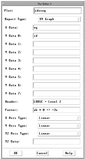
In the setup window, select Plots. Define the idvsvg plot as shown below: |

- The plot table adjusts according to the value of the Report Type field.
| 2 |
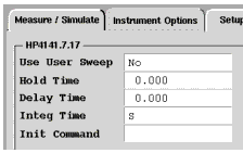
Select Instrument Options to enter the instrument options values. Instruments used in each setup are determined from the instrument unit names specified in the Unit fields of the Input and Output tables. |
Usually only one DC measurement instrument is used in this setup. When using the HP 4141, the window looks similar to the following figure.
Figure 11 Instrument Options for HP 4141
|

|
Add a Macro
You can add a macro to simplify simulations. The example for the MOSFET defines a macro that performs all of the DC simulations together. This macro calls the Simulate function for the large, narrow, and short DUTs.
To define a macro:
| 1 |
In the Model window, select Macros. |

| 3 |
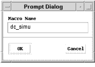
At the prompt, type the macro name, dc_simu. |

| 4 |
Click OK. The new name appears in the macro list. |
| 5 |
To define the macro, type the program directly into the window. |
-
menu_func("large", "Simulate")
menu_func("narrow", "Simulate")
menu_func("lshort", "Simulate")
- To execute the macro, click Execute.

- When you execute this macro, all three DC DUTs (large, narrow, and short) are simulated.
|
Note
|
|
|
|
|
You can also execute macros from the Model window's Macro menu. Click on Macros > Execute, the click on the macro you want to execute. This is useful if you want to execute a macro, and you do not have the Macro folder open.
|
|
Create Other DUTs and Setups
You can create other DUTs and setups by repeating the example procedure. Or, you can build a complete model by copying portions of the supplied model and then modifying any parts of the new setup that needs to be changed to achieve the desired behavior. For the MOSFET model, you can copy the entire large DUT to two new DUTs named narrow and short. In the short DUT, the idvg setup can be copied to a new Setup named idvd. After making the necessary modifications, you have the complete set of DUTs and setups necessary for DC MOSFET characterization. For details, refer to Copying Parts of a Model.
|


