Print version of this Book (PDF file)
Description of the System
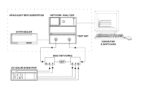
The Agilent 85122A microwave parameter extraction system is specially designed for use with Agilent 85190-series high-frequency IC-CAP software (and a compatible controller) to measure the DC and high-frequency performance of active devices. The software is then used to extract the device model parameters. The standard system uses an Agilent 8510C network analyzer subsystem for S-parameter device characterization from 45 MHz to 20 GHz, and an Agilent 4142B DC source/monitor to provide precision DC characterization as well as bias for the S-parameter measurements.
The synthesized sweeper in the Agilent 8510 subsystem supplies RF signals. The Agilent 4142B DC source/monitor provides DC force (supply) and sense (measure) capability from its plug-in SMUs (source/monitor units). The DC signals are routed via cable feedthrough panels to the Agilent 11612 option Kxx external bias networks. The RF signals are also connected to the bias networks, and thus RF and DC signals are applied together to the device under test. The bias networks have 3.5 mm (female) connectors for interface to a test fixture or probe station.
The system can also be custom-configured to meet individual needs, to provide different operating frequency ranges, bias power levels, or cabling configurations, for example. Or it may include instrumentation for different types of measurements, such as power or noise figure measurements.
The system is factory-installed in a rack. A rack-mounted work surface is included, for maximum convenience in making on-wafer, in-fixture, or coaxial measurements. The work surface is coated with antistatic material and is connected to chassis ground, therefore a static mat is not required.
The following figure shows the general configuration of a typical high-frequency modeling system, although the Agilent 85122A system is installed in a system rack.