Print version of this Book (PDF file)
Noise Measurement Setup
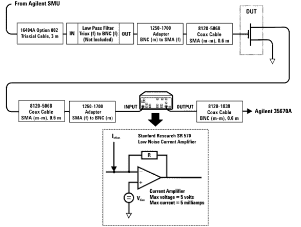
The figure below shows the block diagram of the measurement setup. The input bias is applied by a 4142 (or 4156) parametric analyzer and a 1Hz or a 10 Hz filter. The filter eliminates the line noise from the bias source. When measuring bipolar devices, the filter output impedance, which is typically 50 ohm, has to be increased since such a low value would short circuit the current noise source at the input.
Figure 231 1/f Noise Measurement Setup
The device output is directly connected to the SR570 low noise amplifier. Besides amplifying the output noise, the amplifier provides a current and a voltage supply which are used to bias the device output. The voltage supply allows the setting of the collector or drain voltage while the current source provides an offset current which is used to bias the device. The reason for using the current compensation is that the amplifier works best when the feedback current is minimal (the feedback current flows through R into the device to create the virtual null at the amplifier input). The SR570 can supply an output voltage of up to 5 V and a maximum current compensation of 5 mA.
The gain (expressed in terms of sensitivity A/V) can be varied between 10e-3 to 10e-12 A/V. For this application, since the amplifier bandwidth decreases with the sensitivity, only the higher sensitivities which ensure bandwidth of at least 1 KHz are actually used.
The device 1/f noise is amplified and measured by the 35670A dynamic signal analyzer. This instrument is ideal for analyzing signals with a low frequency power spectrum (such as 1/f noise) as opposed to a spectrum analyzer which is used at higher frequency bands. Because of the relatively low frequency range, the dynamic signal analyzer can directly sample the signal over a 1/f period and operate a FFT transform to calculate the spectral density.
