Print version of this Book (PDF file)
1/f (Flicker Noise) Modeling
The state of the art of 1/f noise modeling will be reviewed, and then the 1/f noise setup will be described with more details. The 1/f noise spectral power density is given by [8]:
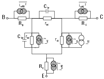
where Kf and Af are the model parameters that needs to be extracted, I is the current flowing through the junction where the flicker noise is generated. The figure below shows the small signal equivalent circuits of bipolar and MOS transistors. All the noise sources, including thermal and shot, are represented. In bipolar transistors the noise is generated by the recombination current in the base, therefore ![]() . The 1/f noise is represented by the current source Inb. Its squared mean value is given by:
. The 1/f noise is represented by the current source Inb. Its squared mean value is given by:
where B is the frequency band of interest.
In FET and MOS devices the noise is generated in the channel, therefore I = Ib. In the MOS equivalent circuit shown below, the 1/f noise is represented by the current source Ind. The expression for the density is:
The bipolar equivalent circuit used is shown below.
The BSIM3 and BSIM4 models for MOSFETs offer, as an alternative, a more complex description which includes other device parameters. As with the conventional BSIM3 and BSIM4 formulation in equation (3), some models (e.g., VBIC) also offer a parameter Ef to model the 1/f slope. The goal is to be able to measure the noise spectrum at low frequencies, where the 1/f noise is dominant, and at several bias points in order to extract the parameters Kf and Af.
Kf is determined by the power vs. frequency characteristics; Af is extracted by varying the bias current.
In both cases, bipolar or MOS, the noise phenomena is related to the current flowing through the device. The formulation gives the spectral density of a random noise current source. The bipolar transistor is by nature a current amplifier. The equivalent circuit is shown above.
Figure 230 Equivalent Circuit of a MOS Transistor
The power noise spectrum of the base current is simply amplified by a factor h2fe at the output (hfe is the small signal current gain). Having considered this, the most natural choice for amplifying the device output noise is a current amplifier. The low noise current amplifier converts the output current noise into voltage. This avoids current to voltage conversions in the circuit. These conversions depend on other circuit parameters, and therefore introduce errors.


