Print version of this Book (PDF file)
Parameter Extraction Procedure
As mentioned already, to extract the noise parameters, Af and Kf, the 1/f noise spectral density of the noise current source needs to be measured at various bias points. Since the current amplifier does not have GP-IB control, its settings (bias voltage, current offset and sensitivity) have to be manually set at each bias point. The measurement is therefore semi-automated with the data acquisition and display controlled by IC-CAP. IC-CAP provides different model files for bipolar and MOS 1/f noise, but similar extraction procedures. The procedure consists of three steps and a verification phase.
In the BJT extraction, the Ic vs. Vbe DC traces are measured. This is accomplished by running the step Measure and Simulate DC Data in the GUI sequence. The DC current gain  , and the output conductance gce are calculated using the measured data.
In the MOS extraction, the Id vs. Vd DC traces are measured instead and the output conductance go is calculated.
Based on those data the user is asked to choose the bias points where the 1/f noise will be measured. Running the macro GUI step Measure Noise Data starts the interactive procedure for measuring the noise. For each bias point, the device is first biased at the base after some time that depends on the filter time constant. The operator is then asked to set the collector voltage, current offset and sensitivity on the SR570. The toolkit then calls the dynamic signal analyzer for measurement of the output noise. The spectral noise density at the output of the device is given by:
where Nmeas is the noise measured by the analyzer expressed in ![]() and SR570 is the sensitivity of the amplifier. In the bipolar case, assuming the DC beta is equal to the small signal current gain, the actual spectral power density of the base current noise source is given by:
and SR570 is the sensitivity of the amplifier. In the bipolar case, assuming the DC beta is equal to the small signal current gain, the actual spectral power density of the base current noise source is given by:
The third step is the extraction of the 1/f noise parameters. In the bipolar case, after selecting a set of traces at constant Vc, a macro linearizes equation (1) as follows:
and extracts the Af and Kf using a linear interpolation in the area where 1/f noise is present. Typically, the extraction is performed between 10 and 100 Hz of the 1/f band.
Low pass filter
The filter schematic is shown in the figure below:
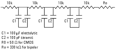
For Noise measurements of bipolar transistors, the low pass filter can be designed using an RC values network with a large output impedance (Ro = 330 kOhm). This large resistance prevents the noise voltage across the base of the transistor from being shorted out. Due to these large value, the filter series resistance is rather large, and so is the RC constant. This large resistance slows down the filter charge, and the device bias time is in the order of minutes. Also, the voltage across the filter might be several volts, therefore the input SMU voltage compliance must be set to a rather high value.
For Noise measurements of MOS transistors, the resistance Ro might be set to 50 ohm. The series resistances of the filter is 30k ohm, so that the filter charging will not be as long as in the bipolar case.