1/f Noise Extraction with MOS Transistors
All previous examples in this chapter have dealt with bipolar junction transistors.
The model selected was
 .../examples/model_files/noise/1_f_toolkit/bjt_1f_noise.mdl.
3For MOS transistors use this model instead
 .../examples/model_files/noise/1_f_toolkit/mos_1f_noise.mdl.
The basic operation for MOS is the same as for bipolar, except where shown in this section.
Some Basic Differences
Terminals The emitter, base and collector terminal are replaced by the source, gate and drain terminals respectively.
Impedances The bipolar transistor has a low input impedance from base to emitter, whereas the gate to source impedance of the MOS transistor is essentially infinite.
Currents The drain current Ids replaces the collector current Ice.
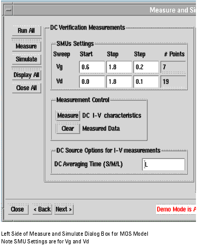
Voltages The voltages Ib and Vce are replaced by Vgs and Vds respectively, as shown in the Measure and Simulate DC Data Dialog Box show below.
Figure 240 LEFT SIDE of Measure and Simulate DC Data Dialog Box
|
|
Three plots are displayed when the Measure and Simulate DC Data Dialog box is launched. The first is Id versus Vd, as shown below. The second plot is gds versus Vd and the third is ig versus Vd.
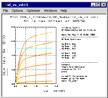
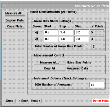
The left side of the Measure Noise Data dialog box is shown below. The difference is that the Noise Bias SMUs Settings are for Vg and Vd, rather than Ib and Vc.
Figure 241 LEFT SIDE of Measure Noise Data Dialog Box
Note SMUs Settings are for Vg and Vd
|
|
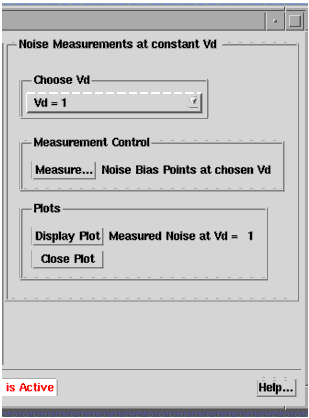
The left side of the Measure Noise Data dialog box is shown below. The difference is that Choose Vd replaces Choose Vc.
Figure 242 RIGHT SIDE of Measure Noise Data
Choose Vd replaces Choose Vc
|
|
The Noise versus Frequency plot shown below is displayed in the Demo Mode when the Measure Noise Data dialog box is launched.
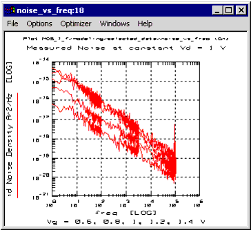
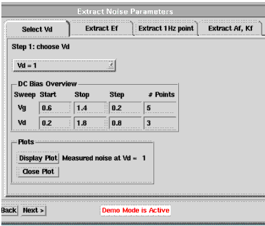
When the Extract Noise Parameters dialog box is launched the previous plot is displayed (also when the Select Vd tab is selected).
Figure 243 With Select Vd tab selected the DC Bias Overview is for Vg and Vd.
|
|
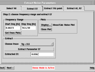
Select the tab Extract Ef. A plot showing measured versus calculated noise will be shown. Choose the frequency range in which you want to perform the Ef extraction. The extraction of the Ef is performed using only one of the noise traces. The Extract box is used to pick the Vg trace to be used, as shown below. Choose a trace and click on Extract Parameter Ef.
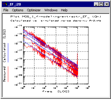
When the Extract Ef tab is selected, the Calculated and Simulated values of Ef versus frequency are displayed, as shown below. So far, only the slopes should match—the y-intersects will be modeled by AF and KF in the next steps.
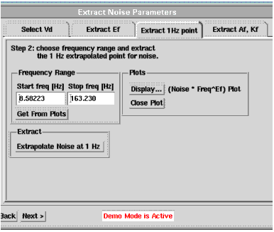
Selecting the Extract 1Hz Point tab produces the page shown below. The plot Noise*freq^Ef vs. frequency is shown. Select the frequency range in which you want to extract the parameters Af and Kf. Choose a range for which the traces are flat.
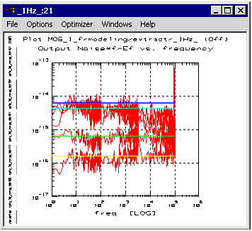
From the Extract 1Hz page the type of plot shown below is produced.
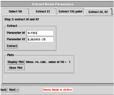
From the Extract Af, Kf page, shown below, a plot of Measured and Calculated Noise versus frequency is produced (shown following dialog box). Click on Extract to extract the parameters Af and Kf in the previously selected frequency range.
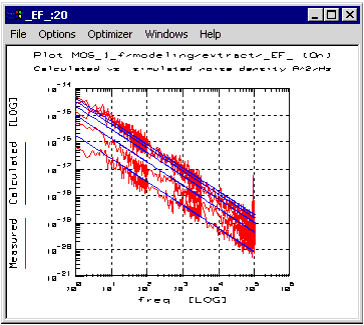
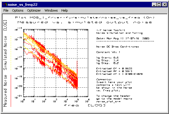
From the Simulate Noise dialog box a plot of Measured and Simulated Noise versus frequency is produced, as shown below.
1/f Noise Function Descriptions
|
|
Noise_1f_bjt_1Hz
|
For each noise trace this function finds the 1 Hz intercept point by calculating the average noise in the specified frequency range. The frequency range can be specified by using the variables X_LOW and X_HIGH. If N is the number of noise traces, the function returns an output dataset of size N filled with the N intercept points (one for each trace).
|
Noise_1f_bjt_calc
|
This function calculates the current noise density at the device output (collector) given the frequency range, the device current gain Bf, the base current and the parameters Af and Kf listed in the Parameters table. The noise is calculated as follows:
<Sic>= Kf * (ib^Af)/f * Beta^2
If N is the number of traces (number of DC bias points) the inputs are defined as follows:
Inputs:
Beta: Dc current gain dataset. Size: N
frequency: Frequency point dataset.
Size: N*freqpoints.
Base Current: Base current dataset. Size: N.
Output:
Dataset filled with the calculated noise.
Size: N*freqpoints.
Examples:
This transform is used during 1/f noise parameters extraction for bipolar devices. See model file
examples/model_files/noise/1_f_toolkit/bjt_1f_noise.mdl The transform is used in the setup modeling/extract.
|
Noise_1f_bjt_extract
|
This function extracts the parameters Af and Kf. If N is the number of noise traces at a given Vc, inputs and output are as follows:
Inputs:
Beta: Dc current gain dataset. Size: N.
Ic noise 1 Hz: 1 Hz intercept dataset. Size: N.
Base Current: base current at each bias point. Size: N.
Output:
Return a dataset of size N with the calculated 1 Hz values using the extracted Af and Kf.
Examples:
This transform is used during 1/f noise parameters extraction for bipolar devices. See model file
examples/model_files/noise/1_f_toolkit/bjt_1f_noise.mdl The transform is used in the setup modeling/extract.
|
Noise_1f_force_bias
|
This function forces a current or a voltage from the specified unit of a 4142B or 4156B/C.
Warning: the instrument will continue to force the bias until the function NOISE_1f_stop_bias is called.
Variables:
GPIB Address: instrument address.
Compliance: voltage or current compliance.
Value: voltage or current value to be forced.
Parameters:
Bias source: specify DC Bias Source Type (4142/4156).
GPIB Interface: interface name.
Unit Slot (4142) or SMU (4156).
Force Current (I) or Voltage (V).
Examples:
re = NOISE_1f_force_bias(29, 2, 25e-6, "4142", "hpib", "2", "I"). This forces 25 uA of current from unit source on slot 2 of the 4142 at address 29. The interface name is "hpib" and the voltage compliance is 2 V.
This transform is used during 1/f noise parameters extraction for bipolar and MOS devices. See model file examples/model_files/noise/1_f_toolkit/bjt_1f_noise.mdl The transform is used in the setup measure/Noise. It is called by the GUI interface function btMeasure located in the setup GuiDriver/MeasureNoise.
|
Noise_1f_get_Af
|
This function returns the value of the parameter
Af/AF/af stored in the parameter list.
Syntax:
x = NOISE_1f_get_Af()
|
Noise_1f_get_Bf
|
This function returns the value of the parameter Bf/BF/bf stored in the parameter list.
Syntax:
x = NOISE_1f_get_Bf()
|
Noise_1f_get_Ef
|
This function returns the value of the parameter Ef/EF/Ef stored in the parameter list.
Syntax:
x = NOISE_1f_get_Ef()
|
Noise_1f_get_Kf
|
This function returns the value of the parameter Kf/KF/kf stored in the parameter list.
Syntax:
x = NOISE_1f_get_Kf()
|
Noise_1f_mos_1hz
|
For each noise trace this function calculates the 1 Hz intercept point by calculating the average noise in the specified frequency range. The frequency range can be specified by using the variables X_LOW and X_HIGH. If N is the number of noise traces, the function returns an output dataset of size N filled with the N intercept points (one for each trace).
|
Noise_1f_set_Af
|
This function sets the value of the parameter Af/AF/af in the parameter list.
Syntax:
NOISE_1f_set_Af(value)
|
Noise_1f_set_Bf
|
This function sets the value of the parameter Bf/BF/bf in the parameter list.
Syntax:
NOISE_1f_set_Bf(value)
|
Noise_1f_set_Ef
|
This function sets the value of the parameter Ef/EF/ef in the parameter list.
Syntax:
NOISE_1f_set_Ef(value)
|
Noise_1f_set_Kf
|
This function sets the value of the parameter Kf/KF/kf in the parameter list.
Syntax:
NOISE_1f_set_Kf(value)
|
Noise_1f_stop_bias
|
This function stops the bias from the specified DC source.
It is used in conjunction with the NOISE_1f_force_bias.
Variables:
GP-IB Address: instrument address.
Parameters:
Bias source: specify DC Bias Source Type (4142/4156).
GPIB Interface: interface name.
Unit Slot (4142) or SMU (4156).
Examples:
ret = NOISE_1f_force_bias(29, "4142", "hpib", "2") the SMU unit at slot 2 of the 4142 at address 29 will stop any voltage or current bias.
This transform is used during 1/f noise parameters extraction for bipolar and MOS devices. See model file examples/model_files/noise/1_f_toolkit/bjt_1f_noise.mdl
The transform is used in the setup measure/Noise. It is called by the GUI interface function btMeasure located in the setup GuiDriver/MeasureNoise.
|
|


