vpr/SRC/base/draw.c File Reference
#include <stdio.h>#include <string.h>#include <math.h>#include "util.h"#include "vpr_types.h"#include "vpr_utils.h"#include "globals.h"#include "graphics.h"#include "path_delay.h"#include "draw.h"#include <assert.h>#include "read_xml_arch_file.h"#include "rr_graph.h" Include dependency graph for draw.c:
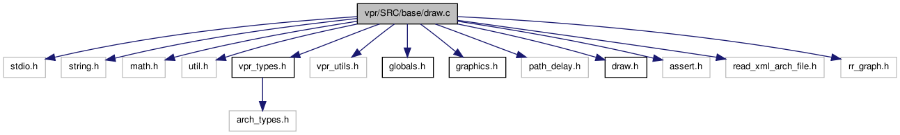
Go to the source code of this file.
Defines | |
| #define | MAX_BLOCK_COLOURS 5 |
Enumerations | |
| enum | e_draw_rr_toggle { DRAW_NO_RR = 0, DRAW_ALL_RR, DRAW_ALL_BUT_BUFFERS_RR, DRAW_NODES_AND_SBOX_RR, DRAW_NODES_RR, DRAW_RR_TOGGLE_MAX } |
| enum | e_draw_net_type { ALL_NETS, HIGHLIGHTED } |
| enum | e_edge_dir { FROM_X_TO_Y, FROM_Y_TO_X } |
Functions | |
| static void | toggle_nets (void(*drawscreen)(void)) |
| static void | toggle_rr (void(*drawscreen)(void)) |
| static void | toggle_defects (void(*drawscreen)(void)) |
| static void | toggle_congestion (void(*drawscreen)(void)) |
| static void | highlight_crit_path (void(*drawscreen_ptr)(void)) |
| static void | drawscreen (void) |
| static void | redraw_screen (void) |
| static void | drawplace (void) |
| static void | drawnets (void) |
| static void | drawroute (enum e_draw_net_type draw_net_type) |
| static void | draw_congestion (void) |
| static void | highlight_blocks (float x, float y) |
| static void | get_block_center (int bnum, float *x, float *y) |
| static void | deselect_all (void) |
| static void | draw_rr (void) |
| static void | draw_rr_edges (int from_node) |
| static void | draw_rr_pin (int inode, enum color_types color) |
| static void | draw_rr_chanx (int inode, int itrack) |
| static void | draw_rr_chany (int inode, int itrack) |
| static void | get_rr_pin_draw_coords (int inode, int iside, int ioff, float *xcen, float *ycen) |
| static void | draw_pin_to_chan_edge (int pin_node, int chan_node) |
| static void | draw_x (float x, float y, float size) |
| static void | draw_chany_to_chany_edge (int from_node, int from_track, int to_node, int to_track, short switch_type) |
| static void | draw_chanx_to_chanx_edge (int from_node, int from_track, int to_node, int to_track, short switch_type) |
| static void | draw_chanx_to_chany_edge (int chanx_node, int chanx_track, int chany_node, int chany_track, enum e_edge_dir edge_dir, short switch_type) |
| static int | get_track_num (int inode, int **chanx_track, int **chany_track) |
| static void | draw_rr_switch (float from_x, float from_y, float to_x, float to_y, boolean buffered) |
| static void | draw_triangle_along_line (float xend, float yend, float x1, float x2, float y1, float y2) |
| void | set_graphics_state (boolean show_graphics_val, int gr_automode_val, enum e_route_type route_type) |
| void | update_screen (int priority, char *msg, enum pic_type pic_on_screen_val, boolean crit_path_button_enabled) |
| void | alloc_draw_structs (void) |
| void | init_draw_coords (float width_val) |
| static void | highlight_nets (char *message) |
| static void | highlight_rr_nodes (float x, float y) |
Variables | |
| static boolean | show_nets = FALSE |
| static enum e_draw_rr_toggle | draw_rr_toggle = DRAW_NO_RR |
| static enum e_route_type | draw_route_type |
| static boolean | show_congestion = FALSE |
| static boolean | show_defects = FALSE |
| static boolean | show_graphics |
| static char | default_message [BUFSIZE] |
| static int | gr_automode |
| static enum pic_type | pic_on_screen = NO_PICTURE |
| static float * | tile_x |
| static float * | tile_y |
| static float | tile_width |
| static float | pin_size |
| static enum color_types * | net_color |
| static enum color_types * | block_color |
| static float | line_fuz = 0.3 |
| static char * | name_type [] |
| static float * | x_rr_node_left = NULL |
| static float * | x_rr_node_right = NULL |
| static float * | y_rr_node_top = NULL |
| static float * | y_rr_node_bottom = NULL |
| static enum color_types * | rr_node_color = NULL |
| static int | old_num_rr_nodes = 0 |
Define Documentation
Enumeration Type Documentation
| enum e_draw_net_type |
| enum e_draw_rr_toggle |
| enum e_edge_dir |
Definition at line 34 of file draw.c.
{ FROM_X_TO_Y, FROM_Y_TO_X }; /* Chanx to chany or vice versa? */
Function Documentation
| void alloc_draw_structs | ( | void | ) |
Allocate the structures needed to draw the placement and routing. Set up the default colors for blocks and nets.
Definition at line 482 of file draw.c.
{
    tile_x = (float *)my_malloc((nx + 2) * sizeof(float));
    tile_y = (float *)my_malloc((ny + 2) * sizeof(float));

    net_color = (enum color_types *)
        my_malloc(num_nets * sizeof(enum color_types));

    block_color = (enum color_types *)
        my_malloc(num_blocks * sizeof(enum color_types));

    x_rr_node_left = (float *) my_malloc(num_rr_nodes*sizeof(float));
    x_rr_node_right = (float *) my_malloc(num_rr_nodes*sizeof(float));
    y_rr_node_top = (float *) my_malloc(num_rr_nodes*sizeof(float));
    y_rr_node_bottom = (float *) my_malloc(num_rr_nodes*sizeof(float));
    rr_node_color = (enum color_types *) my_malloc(num_rr_nodes*sizeof(enum color_types));

    deselect_all();             /* Set initial colors */
}
Here is the call graph for this function: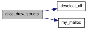 Here is the caller graph for this function:
| static void deselect_all | ( | void | ) | [static] |
Sets the color of all clbs and nets to the default.
Definition at line 2189 of file draw.c.
{
    int i;

    /* Create some colour highlighting */
    for(i = 0; i < num_blocks; i++) {
                if(block[i].type->index < 3) {
                        block_color[i] = LIGHTGREY;
                } else if(block[i].type->index < 3 + MAX_BLOCK_COLOURS) {
                        block_color[i] = BISQUE + MAX_BLOCK_COLOURS + block[i].type->index - 3;
                } else {
                        block_color[i] = BISQUE + 2 * MAX_BLOCK_COLOURS - 1;
                }
        }

    for(i = 0; i < num_nets; i++)
            net_color[i] = BLACK;

    for (i = 0; i < num_rr_nodes; i++)
            rr_node_color[i] = BLACK;
}
Here is the caller graph for this function: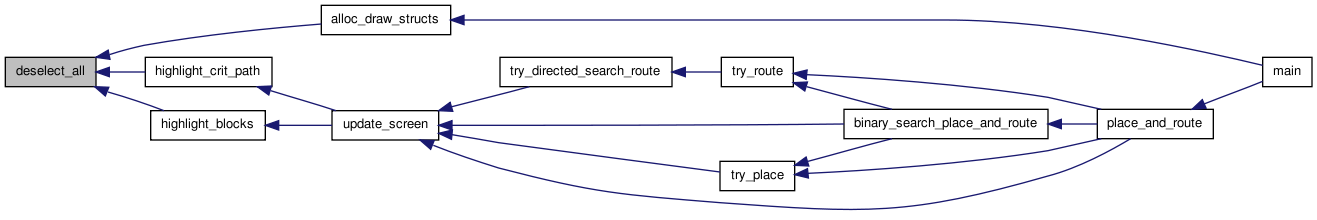
| static void draw_chanx_to_chanx_edge | ( | int | from_node, |
| int | from_track, | ||
| int | to_node, | ||
| int | to_track, | ||
| short | switch_type | ||
| ) | [static] |
Draws a connection between two x-channel segments. Passing in the track numbers allows this routine to be used for both rr_graph and routing drawing.
Definition at line 1376 of file draw.c.
{
    float x1, x2, y1, y2;
    int from_y, to_y, from_xlow, to_xlow, from_xhigh, to_xhigh;

    from_y = rr_node[from_node].ylow;
    from_xlow = rr_node[from_node].xlow;
    from_xhigh = rr_node[from_node].xhigh;
    to_y = rr_node[to_node].ylow;
    to_xlow = rr_node[to_node].xlow;
    to_xhigh = rr_node[to_node].xhigh;

/* (x1, y1) point on from_node, (x2, y2) point on to_node. */

    y1 = tile_y[from_y] + tile_width + 1 + from_track;
    y2 = tile_y[to_y] + tile_width + 1 + to_track;


    if(to_xhigh < from_xlow)
        {                       /* From right to left */
            /* UDSD Note by WMF: could never happen for INC wires, unless U-turn. For DEC
             * wires this handles well */
            x1 = tile_x[from_xlow];
            x2 = tile_x[to_xhigh] + tile_width;
        }
    else if(to_xlow > from_xhigh)
        {                       /* From left to right */
            /* UDSD Note by WMF: could never happen for DEC wires, unless U-turn. For INC
             * wires this handles well */
            x1 = tile_x[from_xhigh] + tile_width;
            x2 = tile_x[to_xlow];
        }

/* Segments overlap in the channel.  Figure out best way to draw.  Have to  *
 * make sure the drawing is symmetric in the from rr and to rr so the edges *
 * will be drawn on top of each other for bidirectional connections.        */

    /* UDSD Modification by WMF Begin */
    else
        {
            if(rr_node[to_node].direction != BI_DIRECTION)
                {
                    /* must connect to to_node's wire beginning at x2 */
                    if(to_track % 2 == 0)
                        {       /* INC wire starts at leftmost edge */
                            assert(from_xlow < to_xlow);
                            x2 = tile_x[to_xlow];
                            /* since no U-turns from_track must be INC as well */
                            x1 = tile_x[to_xlow - 1] + tile_width;
                        }
                    else
                        {       /* DEC wire starts at rightmost edge */
                            assert(from_xhigh > to_xhigh);
                            x2 = tile_x[to_xhigh] + tile_width;
                            x1 = tile_x[to_xhigh + 1];
                        }
                }
            else
                {
                    if(to_xlow < from_xlow)
                        {       /* Draw from left edge of one to other */
                            x1 = tile_x[from_xlow];
                            x2 = tile_x[from_xlow - 1] + tile_width;
                        }
                    else if(from_xlow < to_xlow)
                        {
                            x1 = tile_x[to_xlow - 1] + tile_width;
                            x2 = tile_x[to_xlow];
                        }       /* The following then is executed when from_xlow == to_xlow */
                    else if(to_xhigh > from_xhigh)
                        {       /* Draw from right edge of one to other */
                            x1 = tile_x[from_xhigh] + tile_width;
                            x2 = tile_x[from_xhigh + 1];
                        }
                    else if(from_xhigh > to_xhigh)
                        {
                            x1 = tile_x[to_xhigh + 1];
                            x2 = tile_x[to_xhigh] + tile_width;
                        }
                    else
                        {       /* Complete overlap: start and end both align. Draw outside the sbox */
                            x1 = tile_x[from_xlow];
                            x2 = tile_x[from_xlow] + tile_width;
                        }
                }
        }
    /* UDSD Modification by WMF End */
    drawline(x1, y1, x2, y2);

    if(draw_rr_toggle == DRAW_ALL_RR)
        draw_rr_switch(x1, y1, x2, y2, switch_inf[switch_type].buffered);
}
Here is the call graph for this function: Here is the caller graph for this function:
| static void draw_chanx_to_chany_edge | ( | int | chanx_node, |
| int | chanx_track, | ||
| int | chany_node, | ||
| int | chany_track, | ||
| enum e_edge_dir | edge_dir, | ||
| short | switch_type | ||
| ) | [static] |
Draws an edge (SBOX connection) between an x-directed channel and a y-directed channel.
Definition at line 1297 of file draw.c.
{
    float x1, y1, x2, y2;
    int chanx_y, chany_x, chanx_xlow, chany_ylow;

    chanx_y = rr_node[chanx_node].ylow;
    chanx_xlow = rr_node[chanx_node].xlow;
    chany_x = rr_node[chany_node].xlow;
    chany_ylow = rr_node[chany_node].ylow;

    /* (x1,y1): point on CHANX segment, (x2,y2): point on CHANY segment. */

    y1 = tile_y[chanx_y] + tile_width + 1. + chanx_track;
    x2 = tile_x[chany_x] + tile_width + 1. + chany_track;

    if(chanx_xlow <= chany_x)
        {                       /* Can draw connection going right */
            x1 = tile_x[chany_x] + tile_width;
            /* UDSD by AY Start */
            if(rr_node[chanx_node].direction != BI_DIRECTION)
                {
                    if(edge_dir == FROM_X_TO_Y)
                        {
                            if((chanx_track % 2) == 1)
                                {       /* UDSD Modifications by WMF: If dec wire, then going left */
                                    x1 = tile_x[chany_x + 1];
                                }
                        }
                }
            /* UDSD by AY End */
        }
    else
        {                       /* Must draw connection going left. */
            x1 = tile_x[chanx_xlow];
        }

    if(chany_ylow <= chanx_y)
        {                       /* Can draw connection going up. */
            y2 = tile_y[chanx_y] + tile_width;
            /* UDSD by AY Start */
            if(rr_node[chany_node].direction != BI_DIRECTION)
                {
                    if(edge_dir == FROM_Y_TO_X)
                        {
                            if((chany_track % 2) == 1)
                                {       /* UDSD Modifications by WMF: If dec wire, then going down */
                                    y2 = tile_y[chanx_y + 1];
                                }
                        }
                }
            /* UDSD by AY End */
        }
    else
        {                       /* Must draw connection going down. */
            y2 = tile_y[chany_ylow];
        }

    drawline(x1, y1, x2, y2);

    if(draw_rr_toggle != DRAW_ALL_RR)
        return;

    if(edge_dir == FROM_X_TO_Y)
        draw_rr_switch(x1, y1, x2, y2, switch_inf[switch_type].buffered);
    else
        draw_rr_switch(x2, y2, x1, y1, switch_inf[switch_type].buffered);
}
Here is the call graph for this function: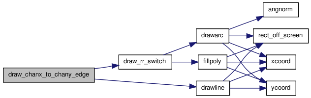 Here is the caller graph for this function:
| static void draw_chany_to_chany_edge | ( | int | from_node, |
| int | from_track, | ||
| int | to_node, | ||
| int | to_track, | ||
| short | switch_type | ||
| ) | [static] |
Draws a connection between two y-channel segments. Passing in the track numbers allows this routine to be used for both rr_graph and routing drawing.
Definition at line 1479 of file draw.c.
{
    float x1, x2, y1, y2;
    int from_x, to_x, from_ylow, to_ylow, from_yhigh, to_yhigh;

    from_x = rr_node[from_node].xlow;
    from_ylow = rr_node[from_node].ylow;
    from_yhigh = rr_node[from_node].yhigh;
    to_x = rr_node[to_node].xlow;
    to_ylow = rr_node[to_node].ylow;
    to_yhigh = rr_node[to_node].yhigh;

/* (x1, y1) point on from_node, (x2, y2) point on to_node. */

    x1 = tile_x[from_x] + tile_width + 1 + from_track;
    x2 = tile_x[to_x] + tile_width + 1 + to_track;

    if(to_yhigh < from_ylow)
        {                       /* From upper to lower */
            y1 = tile_y[from_ylow];
            y2 = tile_y[to_yhigh] + tile_width;
        }
    else if(to_ylow > from_yhigh)
        {                       /* From lower to upper */
            y1 = tile_y[from_yhigh] + tile_width;
            y2 = tile_y[to_ylow];
        }

/* Segments overlap in the channel.  Figure out best way to draw.  Have to  *
 * make sure the drawing is symmetric in the from rr and to rr so the edges *
 * will be drawn on top of each other for bidirectional connections.        */

    /* UDSD Modification by WMF Begin */
    else
        {
            if(rr_node[to_node].direction != BI_DIRECTION)
                {
                    if(to_track % 2 == 0)
                        {       /* INC wire starts at bottom edge */
                            assert(from_ylow < to_ylow);
                            y2 = tile_y[to_ylow];
                            /* since no U-turns from_track must be INC as well */
                            y1 = tile_y[to_ylow - 1] + tile_width;
                        }
                    else
                        {       /* DEC wire starts at top edge */
                            if(!(from_yhigh > to_yhigh))
                                {
                                    printf
                                        ("from_yhigh (%d) !> to_yhigh (%d).\n",
                                         from_yhigh, to_yhigh);
                                    printf
                                        ("from is (%d, %d) to (%d, %d) track %d.\n",
                                         rr_node[from_node].xhigh,
                                         rr_node[from_node].yhigh,
                                         rr_node[from_node].xlow,
                                         rr_node[from_node].ylow,
                                         rr_node[from_node].ptc_num);
                                    printf
                                        ("to is (%d, %d) to (%d, %d) track %d.\n",
                                         rr_node[to_node].xhigh,
                                         rr_node[to_node].yhigh,
                                         rr_node[to_node].xlow,
                                         rr_node[to_node].ylow,
                                         rr_node[to_node].ptc_num);
                                    exit(1);
                                }
                            y2 = tile_y[to_yhigh] + tile_width;
                            y1 = tile_y[to_yhigh + 1];
                        }
                }
            else
                {
                    if(to_ylow < from_ylow)
                        {       /* Draw from bottom edge of one to other. */
                            y1 = tile_y[from_ylow];
                            y2 = tile_y[from_ylow - 1] + tile_width;
                        }
                    else if(from_ylow < to_ylow)
                        {
                            y1 = tile_y[to_ylow - 1] + tile_width;
                            y2 = tile_y[to_ylow];
                        }
                    else if(to_yhigh > from_yhigh)
                        {       /* Draw from top edge of one to other. */
                            y1 = tile_y[from_yhigh] + tile_width;
                            y2 = tile_y[from_yhigh + 1];
                        }
                    else if(from_yhigh > to_yhigh)
                        {
                            y1 = tile_y[to_yhigh + 1];
                            y2 = tile_y[to_yhigh] + tile_width;
                        }
                    else
                        {       /* Complete overlap: start and end both align. Draw outside the sbox */
                            y1 = tile_y[from_ylow];
                            y2 = tile_y[from_ylow] + tile_width;
                        }
                }
        }
    /* UDSD Modification by WMF End */
    drawline(x1, y1, x2, y2);

    if(draw_rr_toggle == DRAW_ALL_RR)
        draw_rr_switch(x1, y1, x2, y2, switch_inf[switch_type].buffered);
}
Here is the call graph for this function: Here is the caller graph for this function:
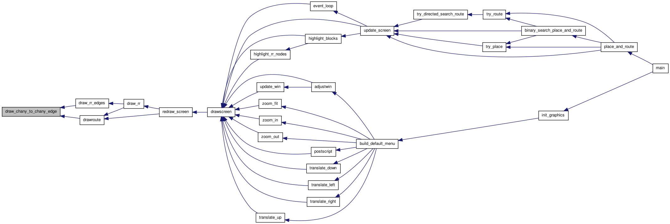
| static void draw_congestion | ( | void | ) | [static] |
Draws all the overused routing resources (i.e. congestion) in RED.
Definition at line 759 of file draw.c.
{
    int inode, itrack;

    setcolor(RED);
    setlinewidth(2);

    for(inode = 0; inode < num_rr_nodes; inode++)
        {
            if(rr_node[inode].occ > rr_node[inode].capacity)
                {
                    switch (rr_node[inode].type)
                        {
                        case CHANX:
                            itrack = rr_node[inode].ptc_num;
                            draw_rr_chanx(inode, itrack);
                            break;

                        case CHANY:
                            itrack = rr_node[inode].ptc_num;
                            draw_rr_chany(inode, itrack);
                            break;

                        case IPIN:
                        case OPIN:
                            draw_rr_pin(inode, RED);
                            break;
                        default:
                                break;
                        }
                }
        }
}
Here is the call graph for this function: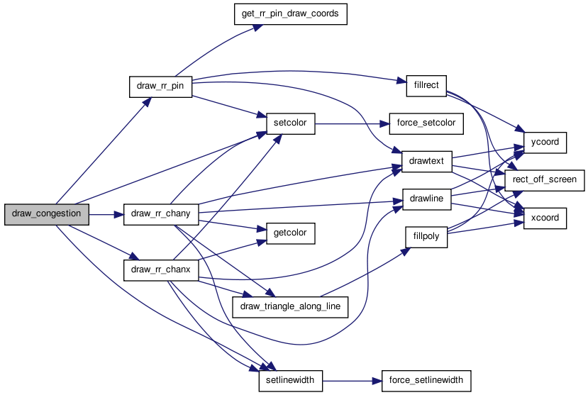 Here is the caller graph for this function:
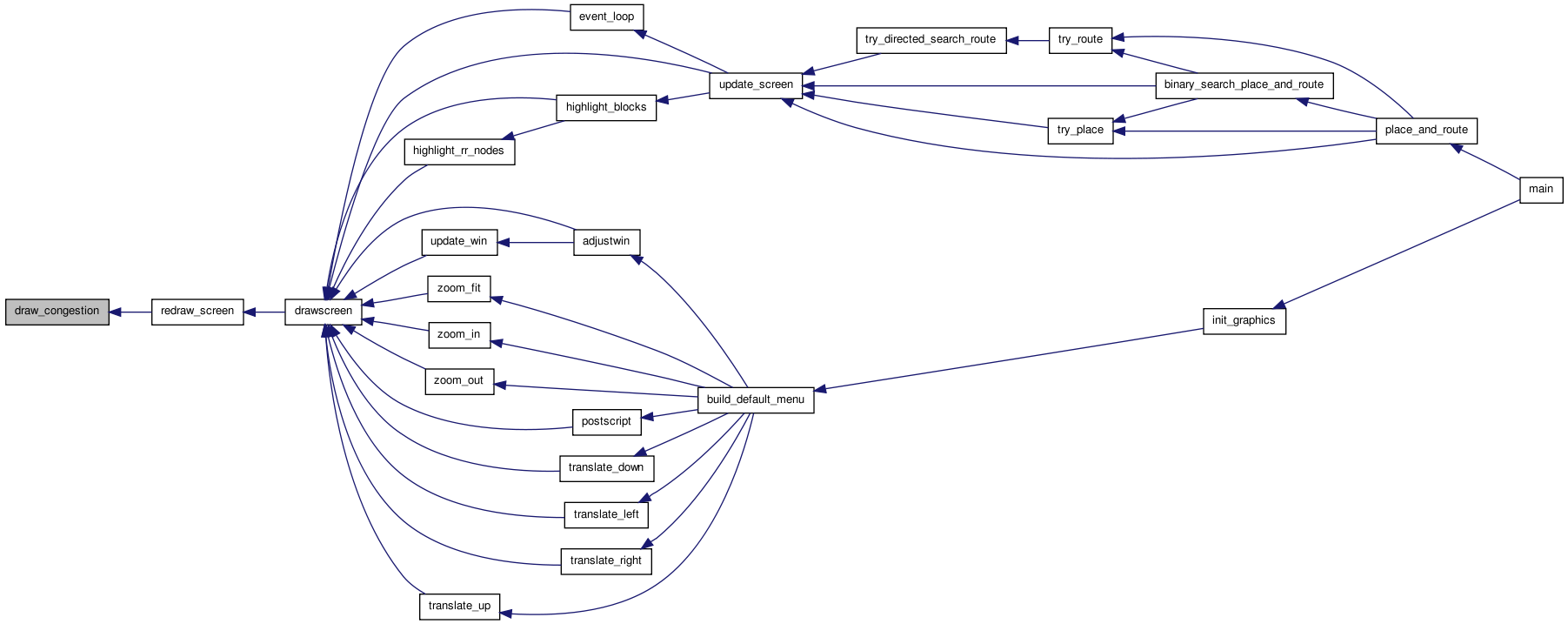
| static void draw_pin_to_chan_edge | ( | int | pin_node, |
| int | chan_node | ||
| ) | [static] |
This routine draws an edge from the pin_node to the chan_node (CHANX or CHANY). The connection is made to the nearest end of the track instead of perpundicular to the track to symbolize a single-drive connection. If mark_conn is TRUE, draw a box where the pin connects to the track (useful for drawing the rr graph)
Definition at line 2254 of file draw.c.
{
/* TODO: Fix this for global routing, currently for detailed only */

    t_rr_type chan_type;
    int grid_x, grid_y, pin_num, chan_xlow, chan_ylow, ioff, height;
    float x1, x2, y1, y2;
    int start, end, i;
    int itrack;
    float xend, yend;
    float draw_pin_off;
    enum e_direction direction;
    enum e_side iside;
    t_type_ptr type;

    direction = rr_node[chan_node].direction;
    grid_x = rr_node[pin_node].xlow;
    grid_y = rr_node[pin_node].ylow;
    pin_num = rr_node[pin_node].ptc_num;
    chan_type = rr_node[chan_node].type;
    itrack = rr_node[chan_node].ptc_num;
    type = grid[grid_x][grid_y].type;

    ioff = grid[grid_x][grid_y].offset;
    /* large block begins at primary tile (offset == 0) */
    grid_y = grid_y - ioff;
    height = grid[grid_x][grid_y].type->height;
    chan_ylow = rr_node[chan_node].ylow;
    chan_xlow = rr_node[chan_node].xlow;
    start = -1;
    end = -1;


    switch (chan_type)
        {

        case CHANX:
            start = rr_node[chan_node].xlow;
            end = rr_node[chan_node].xhigh;
            if(is_opin(pin_num, type))
                {
                    if(direction == INC_DIRECTION)
                        {
                            end = rr_node[chan_node].xlow;
                        }
                    else if(direction == DEC_DIRECTION)
                        {
                            start = rr_node[chan_node].xhigh;
                        }
                }

            start = max(start, grid_x);
            end = min(end, grid_x);     /* Width is 1 always */
            assert(end >= start);       /* Make sure we are nearby */

            if((grid_y + height - 1) == chan_ylow)
                {
                    iside = TOP;
                    ioff = height - 1;
                    draw_pin_off = pin_size;
                }
            else
                {
                    assert((grid_y - 1) == chan_ylow);

                    iside = BOTTOM;
                    ioff = 0;
                    draw_pin_off = -pin_size;
                }
            assert(grid[grid_x][grid_y].type->pinloc[ioff][iside][pin_num]);

            get_rr_pin_draw_coords(pin_node, iside, ioff, &x1, &y1);
            y1 += draw_pin_off;

            y2 = tile_y[rr_node[chan_node].ylow] + tile_width + 1. + itrack;
            x2 = x1;
            if(is_opin(pin_num, type))
                {
                    if(direction == INC_DIRECTION)
                        {
                            x2 = tile_x[rr_node[chan_node].xlow];
                        }
                    else if(direction == DEC_DIRECTION)
                        {
                            x2 = tile_x[rr_node[chan_node].xhigh] +
                                tile_width;
                        }
                }
            break;

        case CHANY:
            start = rr_node[chan_node].ylow;
            end = rr_node[chan_node].yhigh;
            if(is_opin(pin_num, type))
                {
                    if(direction == INC_DIRECTION)
                        {
                            end = rr_node[chan_node].ylow;
                        }
                    else if(direction == DEC_DIRECTION)
                        {
                            start = rr_node[chan_node].yhigh;
                        }
                }

            start = max(start, grid_y);
            end = min(end, (grid_y + height - 1));      /* Width is 1 always */
            assert(end >= start);       /* Make sure we are nearby */

            if((grid_x) == chan_xlow)
                {
                    iside = RIGHT;
                    draw_pin_off = pin_size;
                }
            else
                {
                    assert((grid_x - 1) == chan_xlow);
                    iside = LEFT;
                    draw_pin_off = -pin_size;
                }
            for(i = start; i <= end; i++)
                {
                    ioff = i - grid_y;
                    assert(ioff >= 0 && ioff < type->height);
                    /* Once we find the location, break out, this will leave ioff pointing
                     * to the correct offset.  If an offset is not found, the assertion after
                     * this will fail.  With the correct routing graph, the assertion will not
                     * be triggered.  This also takes care of connecting a wire once to multiple
                     * physical pins on the same side. */
                    if(grid[grid_x][grid_y].type->
                       pinloc[ioff][iside][pin_num])
                        {
                            break;
                        }
                }
            assert(grid[grid_x][grid_y].type->pinloc[ioff][iside][pin_num]);

            get_rr_pin_draw_coords(pin_node, iside, ioff, &x1, &y1);
            x1 += draw_pin_off;

            x2 = tile_x[chan_xlow] + tile_width + 1 + itrack;
            y2 = y1;
            if(is_opin(pin_num, type))
                {
                    if(direction == INC_DIRECTION)
                        {
                            y2 = tile_y[rr_node[chan_node].ylow];
                        }
                    else if(direction == DEC_DIRECTION)
                        {
                            y2 = tile_y[rr_node[chan_node].yhigh] +
                                tile_width;
                        }
                }
            break;

        default:
            printf
                ("Error in draw_pin_to_chan_edge:  invalid channel node %d.\n",
                 chan_node);
            exit(1);
        }

    drawline(x1, y1, x2, y2);
    if(direction == BI_DIRECTION || !is_opin(pin_num, type))
        {
            draw_x(x2, y2, 0.7 * pin_size);
        }
    else
        {
            xend = x2 + (x1 - x2) / 10.;
            yend = y2 + (y1 - y2) / 10.;
            draw_triangle_along_line(xend, yend, x1, x2, y1, y2);
        }
}
Here is the call graph for this function: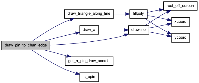 Here is the caller graph for this function:
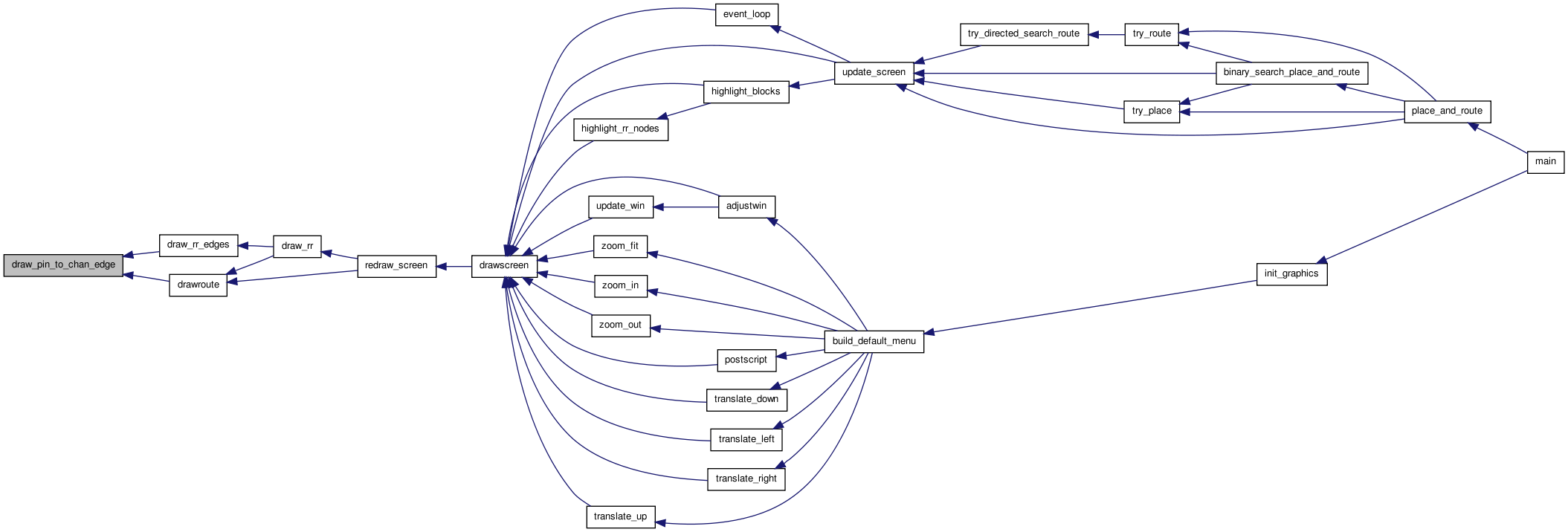
| void draw_rr | ( | void | ) | [static] |
Draws the routing resources that exist in the FPGA, if the user wants them drawn.
Definition at line 798 of file draw.c.
{
    int inode, itrack;

    if(draw_rr_toggle == DRAW_NO_RR)
        {
            setlinewidth(3);
            drawroute(HIGHLIGHTED);
            setlinewidth(0);
            return;
        }

    setlinestyle(SOLID);
    setlinewidth(0);

    for(inode = 0; inode < num_rr_nodes; inode++)
        {
            switch (rr_node[inode].type)
                {

                case SOURCE:
                case SINK:
                    break;      /* Don't draw. */

                case CHANX:
                    if(show_defects && (rr_node[inode].capacity <= 0))
                            setcolor(RED);
                    else
                            setcolor(BLACK);
                    if(show_defects && (rr_node[inode].occ > 0))
                            setcolor(CYAN);
                    itrack = rr_node[inode].ptc_num;
                    draw_rr_chanx(inode, itrack);
                    draw_rr_edges(inode);
                    break;

                case CHANY:
                    if(show_defects && (rr_node[inode].capacity <= 0))
                            setcolor(RED);
                    else
                            setcolor (BLACK);
                    if(show_defects && (rr_node[inode].occ > 0))
                            setcolor(CYAN);
                    itrack = rr_node[inode].ptc_num;
                    draw_rr_chany(inode, itrack);
                    draw_rr_edges(inode);
                    break;

                case IPIN:
                    if(show_defects)
                    {
                            if(rr_node[inode].capacity < 0)
                                    draw_rr_pin(inode, RED);
                            else if(rr_node[inode].occ > 0)
                                    draw_rr_pin(inode, CYAN);
                            else
                                    draw_rr_pin(inode, BLACK);
                    }
                    else
                            draw_rr_pin(inode, BLUE);
                    break;

                case OPIN:
                    if(show_defects)
                    {
                            if(rr_node[inode].capacity < 0)
                                    draw_rr_pin(inode, RED);
                            else if(rr_node[inode].occ > 0)
                                    draw_rr_pin(inode, CYAN);
                            else
                                    draw_rr_pin(inode, BLACK);
                            setcolor(BLACK);
                    }
                    else
                    {
                            draw_rr_pin(inode, RED);
                            setcolor(RED);
                    }
                    setcolor(RED);
                    draw_rr_edges(inode);
                    break;

                default:
                    printf
                        ("Error in draw_rr:  Unexpected rr_node type: %d.\n",
                         rr_node[inode].type);
                    exit(1);
                }
        }

    setlinewidth(3);
    drawroute(HIGHLIGHTED);
    setlinewidth(0);
}
Here is the call graph for this function: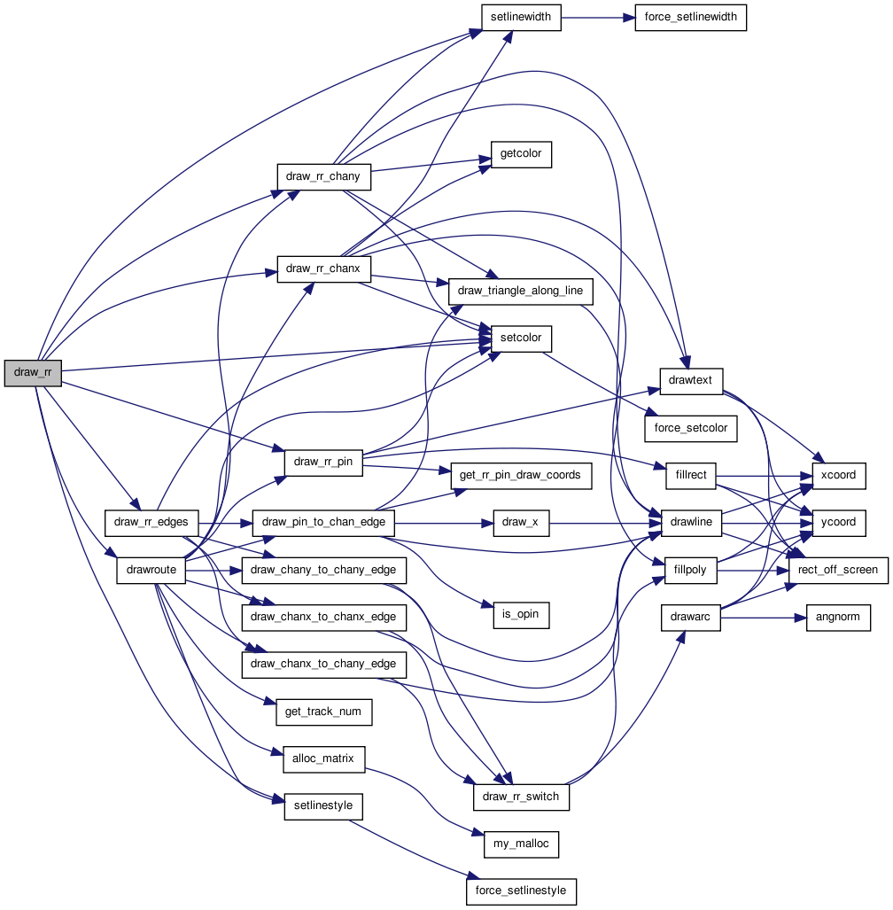 Here is the caller graph for this function:
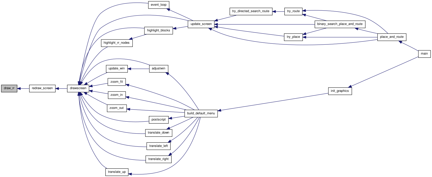
| static void draw_rr_chanx | ( | int | inode, |
| int | itrack | ||
| ) | [static] |
Draws an x-directed channel segment.
Definition at line 896 of file draw.c.
{
    enum
    { BUFFSIZE = 80 };
    float x1, x2, y;
    float y1, y2;               /* UDSD by AY */
    int k;                      /* UDSD by AY */
    char str[BUFFSIZE];
        int savecolor;

    /* Track 0 at bottom edge, closest to "owning" clb. */

    x1 = tile_x[rr_node[inode].xlow];
    x2 = tile_x[rr_node[inode].xhigh] + tile_width;
    y = tile_y[rr_node[inode].ylow] + tile_width + 1.0 + itrack;
    x_rr_node_left[inode] = x1;
    x_rr_node_right[inode] = x2;
    y_rr_node_bottom[inode] = y - line_fuz;
    y_rr_node_top[inode] = y + line_fuz;
    if(rr_node_color[inode] != BLACK)
    {
            savecolor=getcolor();
            setcolor(rr_node_color[inode]);
            setlinewidth(3);
            drawline(x1, y, x2, y);
            setlinewidth(0);
            setcolor(savecolor);
    }
    else
    {
            drawline(x1, y, x2, y);
    }
    /* UDSD by AY Start */
    y1 = y - 0.25;
    y2 = y + 0.25;

    if(rr_node[inode].direction == INC_DIRECTION)
        {
            setlinewidth(2);
            setcolor(YELLOW);
            drawline(x1, y1, x1, y2);   /* Draw a line at start of wire to indicate mux */

            /* Mux balence numbers */
            setcolor(BLACK);
            sprintf(str, "%d", rr_node[inode].fan_in);
            drawtext(x1, y, str, 5);

            setcolor(BLACK);
            setlinewidth(0);
            draw_triangle_along_line(x2 - 0.15, y, x1, x2, y, y);

            setcolor(LIGHTGREY);
            /* TODO: this looks odd, why does it ignore final block? does this mean nothing appears with L=1 ? */
            for(k = rr_node[inode].xlow; k < rr_node[inode].xhigh; k++)
                {
                    x2 = tile_x[k] + tile_width;
                    draw_triangle_along_line(x2 - 0.15, y, x1, x2, y, y);
                    x2 = tile_x[k + 1];
                    draw_triangle_along_line(x2 + 0.15, y, x1, x2, y, y);
                }
            setcolor(BLACK);
        }
    else if(rr_node[inode].direction == DEC_DIRECTION)
        {
            setlinewidth(2);
            setcolor(YELLOW);
            drawline(x2, y1, x2, y2);

            /* Mux balance numbers */
            setcolor(BLACK);
            sprintf(str, "%d", rr_node[inode].fan_in);
            drawtext(x2, y, str, 5);

            setlinewidth(0);
            draw_triangle_along_line(x1 + 0.15, y, x2, x1, y, y);
            setcolor(LIGHTGREY);
            for(k = rr_node[inode].xhigh; k > rr_node[inode].xlow; k--)
                {
                    x1 = tile_x[k];
                    draw_triangle_along_line(x1 + 0.15, y, x2, x1, y, y);
                    x1 = tile_x[k - 1] + tile_width;
                    draw_triangle_along_line(x1 - 0.15, y, x2, x1, y, y);
                }
            setcolor(BLACK);
        }
    /* UDSD by AY End */
}
Here is the call graph for this function: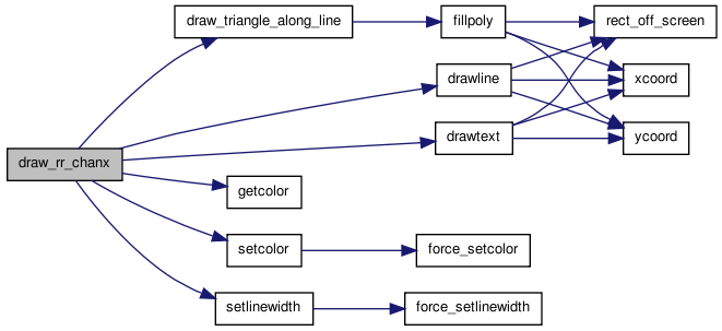 Here is the caller graph for this function:
| static void draw_rr_chany | ( | int | inode, |
| int | itrack | ||
| ) | [static] |
Draws a y-directed channel segment.
Definition at line 988 of file draw.c.
{
    enum
    { BUFFSIZE = 80 };
    float x, y1, y2;
    float x1, x2;               /* UDSD by AY */
    int k;                      /* UDSD by AY */
    char str[BUFFSIZE];
        int savecolor;

    /* Track 0 at left edge, closest to "owning" clb. */

    x = tile_x[rr_node[inode].xlow] + tile_width + 1. + itrack;
    y1 = tile_y[rr_node[inode].ylow];
    y2 = tile_y[rr_node[inode].yhigh] + tile_width;
    x_rr_node_left[inode] = x - line_fuz;
    x_rr_node_right[inode] = x + line_fuz;
    y_rr_node_bottom[inode] = y1;
    y_rr_node_top[inode] = y2;
    if(rr_node_color[inode] != BLACK)
    {
            savecolor=getcolor();
            setcolor(rr_node_color[inode]);
            setlinewidth(3);
            drawline(x, y1, x, y2);
            setlinewidth(0);
            setcolor(savecolor);
    }
    else
    {
            drawline(x, y1, x, y2);
    }

    /* UDSD by AY Start */
    x1 = x - 0.25;
    x2 = x + 0.25;
    if(rr_node[inode].direction == INC_DIRECTION)
        {
            setlinewidth(2);
            setcolor(YELLOW);
            drawline(x1, y1, x2, y1);

            /* UDSD Modifications by WMF Begin */
            setcolor(BLACK);
            sprintf(str, "%d", rr_node[inode].fan_in);
            drawtext(x, y1, str, 5);
            setcolor(BLACK);
            /* UDSD Modifications by WMF End */

            setlinewidth(0);
            draw_triangle_along_line(x, y2 - 0.15, x, x, y1, y2);
            setcolor(LIGHTGREY);
            for(k = rr_node[inode].ylow; k < rr_node[inode].yhigh; k++)
                {
                    y2 = tile_y[k] + tile_width;
                    draw_triangle_along_line(x, y2 - 0.15, x, x, y1, y2);
                    y2 = tile_y[k + 1];
                    draw_triangle_along_line(x, y2 + 0.15, x, x, y1, y2);
                }
            setcolor(BLACK);
        }
    else if(rr_node[inode].direction == DEC_DIRECTION)
        {
            setlinewidth(2);
            setcolor(YELLOW);
            drawline(x1, y2, x2, y2);

            /* UDSD Modifications by WMF Begin */
            setcolor(BLACK);
            sprintf(str, "%d", rr_node[inode].fan_in);
            drawtext(x, y2, str, 5);
            setcolor(BLACK);
            /* UDSD Modifications by WMF End */

            setlinewidth(0);
            draw_triangle_along_line(x, y1 + 0.15, x, x, y2, y1);
            setcolor(LIGHTGREY);
            for(k = rr_node[inode].yhigh; k > rr_node[inode].ylow; k--)
                {
                    y1 = tile_y[k];
                    draw_triangle_along_line(x, y1 + 0.15, x, x, y2, y1);
                    y1 = tile_y[k - 1] + tile_width;
                    draw_triangle_along_line(x, y1 - 0.15, x, x, y2, y1);
                }
            setcolor(BLACK);
        }
    /* UDSD by AY End */
}
Here is the call graph for this function: Here is the caller graph for this function:
| static void draw_rr_edges | ( | int | inode | ) | [static] |
Draws all the edges that the user wants shown between inode and what it connects to. inode is assumed to be a CHANX, CHANY, or OPIN.
Definition at line 1083 of file draw.c.
{
t_rr_type from_type, to_type;
int iedge, to_node, from_ptc_num, to_ptc_num;
short switch_type;
boolean defective=FALSE;
from_type = rr_node[inode].type;
if((draw_rr_toggle == DRAW_NODES_RR) ||
(draw_rr_toggle == DRAW_NODES_AND_SBOX_RR && from_type == OPIN))
{
return; /* Nothing to draw. */
}
from_ptc_num = rr_node[inode].ptc_num;
for(iedge = 0; iedge < rr_node[inode].num_edges; iedge++)
{
to_node = rr_node[inode].edges[iedge];
to_type = rr_node[to_node].type;
to_ptc_num = rr_node[to_node].ptc_num;
if(show_defects)
defective = (switch_inf[rr_node[inode].switches[iedge]].R < 0);
switch (from_type)
{
case OPIN:
switch (to_type)
{
case CHANX:
case CHANY:
if(show_defects)
{
if(defective)
setcolor(RED);
else
setcolor(BLACK);
}
else
setcolor(RED);
draw_pin_to_chan_edge(inode, to_node);
break;
default:
printf
("Error in draw_rr_edges: node %d (type: %d) connects to \n"
"node %d (type: %d).\n", inode, from_type,
to_node, to_type);
exit(1);
break;
}
break;
case CHANX: /* from_type */
switch (to_type)
{
case IPIN:
if(draw_rr_toggle == DRAW_NODES_AND_SBOX_RR)
{
break;
}
if(show_defects)
{
if(defective)
setcolor(RED);
else
setcolor(BLACK);
}
else
setcolor(BLUE);
draw_pin_to_chan_edge(to_node, inode);
break;
case CHANX:
if(show_defects)
{
if(defective)
setcolor(RED);
else
setcolor(BLACK);
}
else
setcolor(DARKGREEN);
switch_type = rr_node[inode].switches[iedge];
draw_chanx_to_chanx_edge(inode, from_ptc_num,
to_node, to_ptc_num,
switch_type);
break;
case CHANY:
if(show_defects)
{
if(defective)
setcolor(RED);
else
setcolor(BLACK);
}
else
setcolor(DARKGREEN);
switch_type = rr_node[inode].switches[iedge];
draw_chanx_to_chany_edge(inode, from_ptc_num,
to_node, to_ptc_num,
FROM_X_TO_Y,
switch_type);
break;
default:
printf
("Error in draw_rr_edges: node %d (type: %d) connects to \n"
"node %d (type: %d).\n", inode, from_type,
to_node, to_type);
exit(1);
break;
}
break;
case CHANY: /* from_type */
switch (to_type)
{
case IPIN:
if(draw_rr_toggle == DRAW_NODES_AND_SBOX_RR)
{
break;
}
if(show_defects)
{
if(defective)
setcolor(RED);
else
setcolor(BLACK);
}
else
setcolor(BLUE);
draw_pin_to_chan_edge(to_node, inode);
break;
case CHANX:
if(show_defects)
{
if(defective)
setcolor(RED);
else
setcolor(BLACK);
}
else
setcolor(DARKGREEN);
switch_type = rr_node[inode].switches[iedge];
draw_chanx_to_chany_edge(to_node, to_ptc_num,
inode, from_ptc_num,
FROM_Y_TO_X,
switch_type);
break;
case CHANY:
if(show_defects)
{
if(defective)
setcolor(RED);
else
setcolor(BLACK);
}
else
setcolor(DARKGREEN);
switch_type = rr_node[inode].switches[iedge];
draw_chany_to_chany_edge(inode, from_ptc_num,
to_node, to_ptc_num,
switch_type);
break;
default:
printf
("Error in draw_rr_edges: node %d (type: %d) connects to \n"
"node %d (type: %d).\n", inode, from_type,
to_node, to_type);
exit(1);
break;
}
break;
default: /* from_type */
printf
("Error: draw_rr_edges called with node %d of type %d.\n",
inode, from_type);
exit(1);
break;
}
} /* End of for each edge loop */
}
Here is the call graph for this function: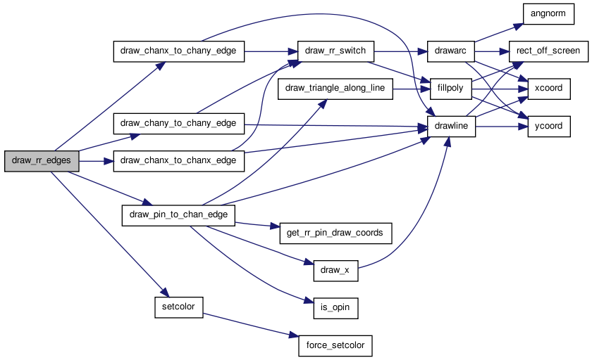 Here is the caller graph for this function:
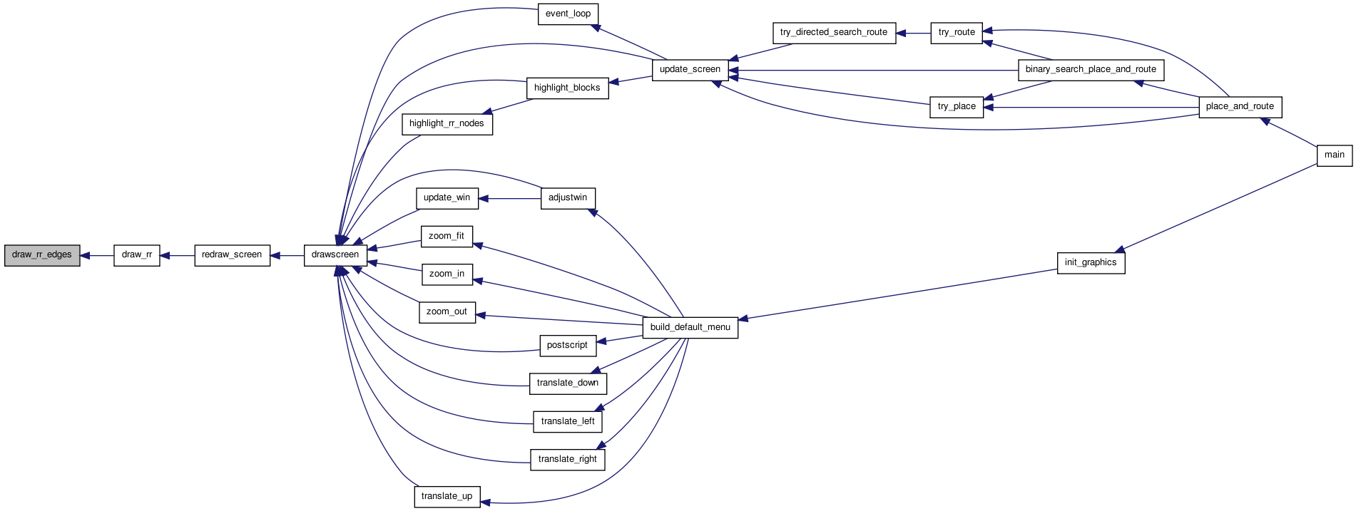
| static void draw_rr_pin | ( | int | inode, |
| enum color_types | color | ||
| ) | [static] |
Draws an IPIN or OPIN rr_node. Note that the pin can appear on more than one side of a clb. Also note that this routine can change the current color to BLACK.
Definition at line 1643 of file draw.c.
{
    int ipin, i, j, iside, iclass, ioff;
    float xcen, ycen;
    char str[BUFSIZE];
    t_type_ptr type;

    i = rr_node[inode].xlow;
    j = rr_node[inode].ylow;
    ipin = rr_node[inode].ptc_num;
    type = grid[i][j].type;
    ioff = grid[i][j].offset;

    setcolor(color);
    iclass = type->pin_class[ipin];
    /* TODO: This is where we can hide fringe physical pins and also identify globals (hide, color, show) */
    for(iside = 0; iside < 4; iside++)
        {
            if(type->pinloc[grid[i][j].offset][iside][ipin])
                {               /* Pin exists on this side. */
                    get_rr_pin_draw_coords(inode, iside, ioff, &xcen, &ycen);
                    fillrect(xcen - pin_size, ycen - pin_size,
                             xcen + pin_size, ycen + pin_size);
                    sprintf(str, "%d", ipin);
                    setcolor(BLACK);
                    drawtext(xcen, ycen, str, 2 * pin_size);
                    setcolor(color);
                }
        }
}
Here is the call graph for this function: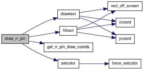 Here is the caller graph for this function:
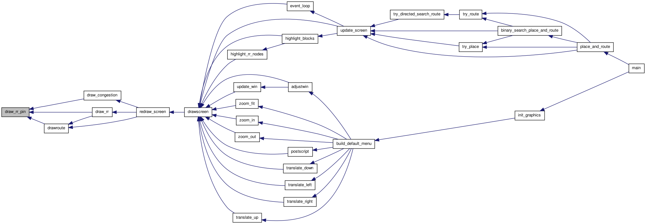
| static void draw_rr_switch | ( | float | from_x, |
| float | from_y, | ||
| float | to_x, | ||
| float | to_y, | ||
| boolean | buffered | ||
| ) | [static] |
Draws a buffer (triangle) or pass transistor (circle) on the edge connecting from to to, depending on the status of buffered. The drawing is closest to the from_node, since it reflects the switch type of from.
Definition at line 1596 of file draw.c.
{
    const float switch_rad = 0.15;
    float magnitude, xcen, ycen, xdelta, ydelta, xbaseline, ybaseline;
    float xunit, yunit;
    t_point poly[3];

    xcen = from_x + (to_x - from_x) / 10.;
    ycen = from_y + (to_y - from_y) / 10.;

    if(!buffered)
        {                       /* Draw a circle for a pass transistor */
            drawarc(xcen, ycen, switch_rad, 0., 360.);
        }
    else
        {                       /* Buffer */
            xdelta = to_x - from_x;
            ydelta = to_y - from_y;
            magnitude = sqrt(xdelta * xdelta + ydelta * ydelta);
            xunit = xdelta / magnitude;
            yunit = ydelta / magnitude;
            poly[0].x = xcen + xunit * switch_rad;
            poly[0].y = ycen + yunit * switch_rad;
            xbaseline = xcen - xunit * switch_rad;
            ybaseline = ycen - yunit * switch_rad;

/* Recall: perpendicular vector to the unit vector along the switch (xv, yv) *
 * is (yv, -xv).                                                             */

            poly[1].x = xbaseline + yunit * switch_rad;
            poly[1].y = ybaseline - xunit * switch_rad;
            poly[2].x = xbaseline - yunit * switch_rad;
            poly[2].y = ybaseline + xunit * switch_rad;
            fillpoly(poly, 3);
        }
}
Here is the call graph for this function: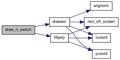 Here is the caller graph for this function:
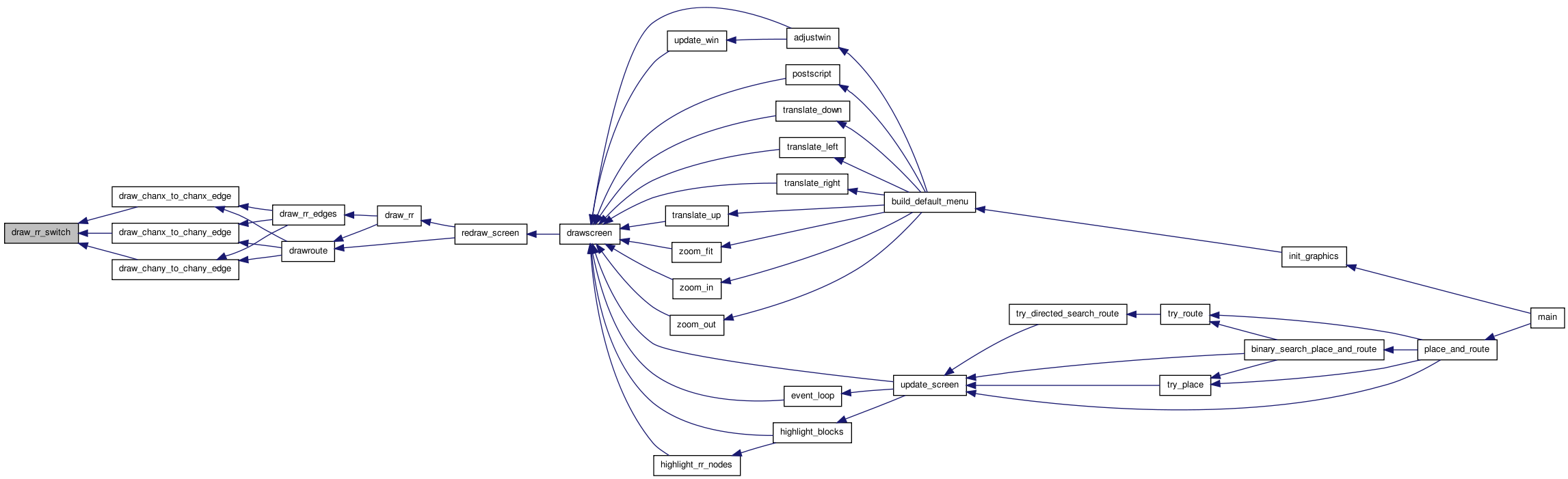
| static void draw_triangle_along_line | ( | float | xend, |
| float | yend, | ||
| float | x1, | ||
| float | x2, | ||
| float | y1, | ||
| float | y2 | ||
| ) | [static] |
Definition at line 2214 of file draw.c.
{
    float switch_rad = 0.15;
    float xdelta, ydelta;
    float magnitude;
    float xunit, yunit;
    float xbaseline, ybaseline;
    t_point poly[3];

    xdelta = x2 - x1;
    ydelta = y2 - y1;
    magnitude = sqrt(xdelta * xdelta + ydelta * ydelta);
    xunit = xdelta / magnitude;
    yunit = ydelta / magnitude;

    poly[0].x = xend + xunit * switch_rad;
    poly[0].y = yend + yunit * switch_rad;
    xbaseline = xend - xunit * switch_rad;
    ybaseline = yend - yunit * switch_rad;
    poly[1].x = xbaseline + yunit * switch_rad;
    poly[1].y = ybaseline - xunit * switch_rad;
    poly[2].x = xbaseline - yunit * switch_rad;
    poly[2].y = ybaseline + xunit * switch_rad;

    fillpoly(poly, 3);
}
Here is the call graph for this function: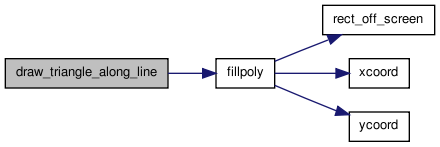 Here is the caller graph for this function:
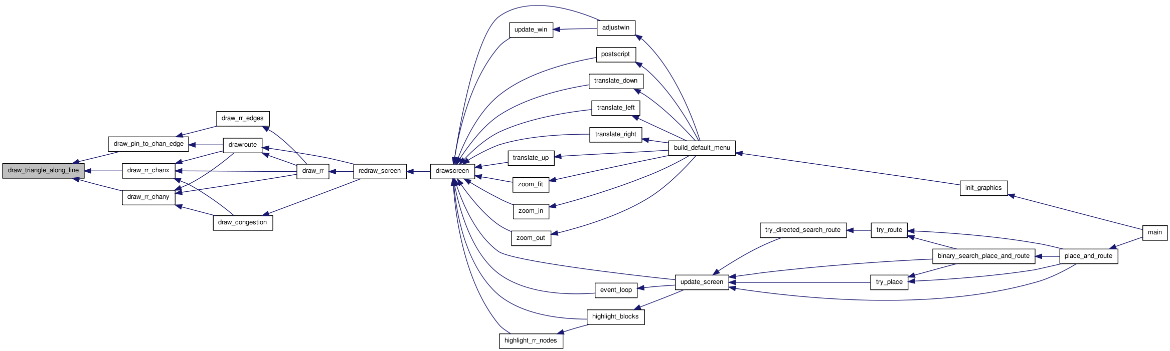
| static void draw_x | ( | float | x, |
| float | y, | ||
| float | size | ||
| ) | [static] |
Draws an X centered at (x,y). The width and height of the X are each 2 * size.
Definition at line 1282 of file draw.c.
{

    drawline(x - size, y + size, x + size, y - size);
    drawline(x - size, y - size, x + size, y + size);
}
Here is the call graph for this function: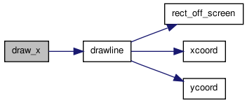 Here is the caller graph for this function:
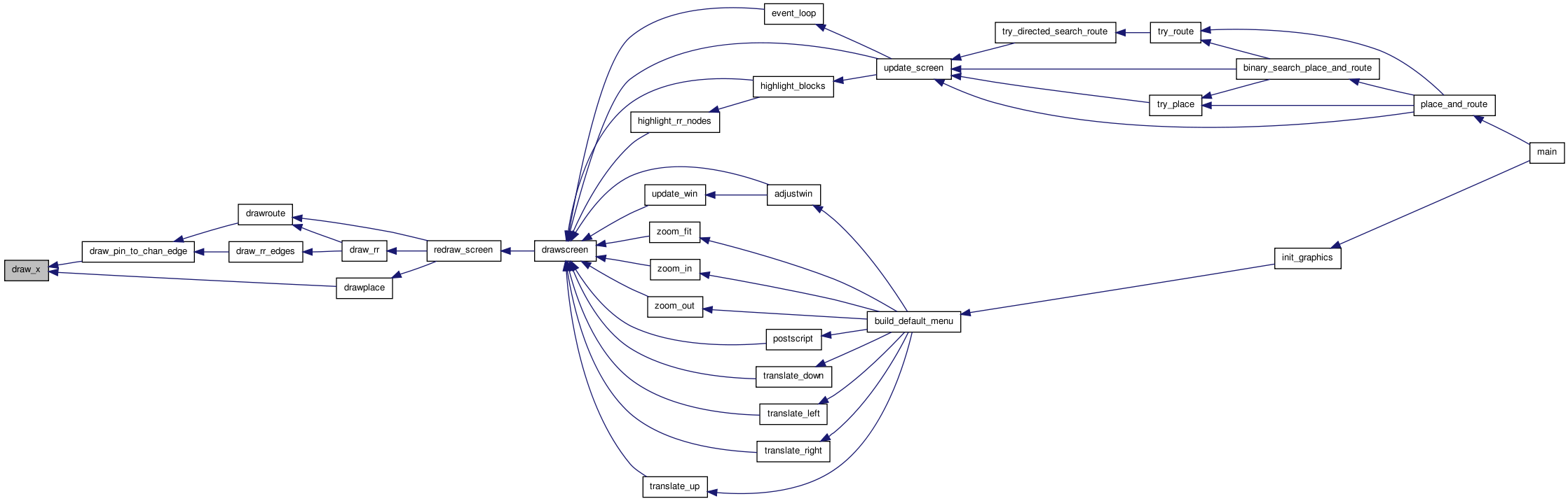
| static void drawnets | ( | void | ) | [static] |
This routine draws the nets on the placement. The nets have not yet been routed, so we just draw a chain showing a possible path for each net. This gives some idea of future congestion.
Definition at line 686 of file draw.c.
{
    int inet, ipin, b1, b2;
    float x1, y1, x2, y2;

    setlinestyle(SOLID);
    setlinewidth(0);

    /* Draw the net as a star from the source to each sink. Draw from centers of *
     * blocks (or sub blocks in the case of IOs).                                */

    for(inet = 0; inet < num_nets; inet++)
        {
            if(clb_net[inet].is_global)
                continue;       /* Don't draw global nets. */

            setcolor(net_color[inet]);
            b1 = clb_net[inet].node_block[0];   /* The DRIVER */
            get_block_center(b1, &x1, &y1);

            for(ipin = 1; ipin < (clb_net[inet].num_sinks + 1); ipin++)
                {
                    b2 = clb_net[inet].node_block[ipin];
                    get_block_center(b2, &x2, &y2);
                    drawline(x1, y1, x2, y2);

                    /* Uncomment to draw a chain instead of a star. */
                    /*      x1 = x2;  */
                    /*      y1 = y2;  */
                }
        }
}
Here is the call graph for this function: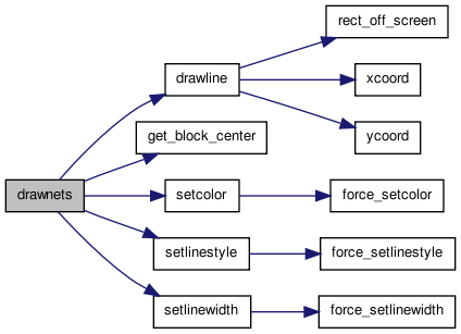 Here is the caller graph for this function:
| static void drawplace | ( | void | ) | [static] |
Draws the blocks placed on the proper clbs. Occupied blocks are darker colours while empty ones are lighter colours and have a dashed border.
Definition at line 568 of file draw.c.
{
    float sub_tile_step;
    float x1, y1, x2, y2;
    int i, j, k, bnum;
    int num_sub_tiles;
    int height;

    setlinewidth(0);

    for(i = 0; i <= (nx + 1); i++)
        {
            for(j = 0; j <= (ny + 1); j++)
                {
                    /* Only the first block of a group should control drawing */
                    if(grid[i][j].offset > 0)
                        continue;

                    /* Don't draw corners */
                    if(((i < 1) || (i > nx)) && ((j < 1) || (j > ny)))
                        continue;

                    num_sub_tiles = grid[i][j].type->capacity;
                    sub_tile_step = tile_width / num_sub_tiles;
                    height = grid[i][j].type->height;

                    if(num_sub_tiles < 1)
                        {
                            setcolor(BLACK);
                            setlinestyle(DASHED);
                            drawrect(tile_x[i], tile_y[j],
                                     tile_x[i] + tile_width,
                                     tile_y[j] + tile_width);
                            draw_x(tile_x[i] + (tile_width / 2),
                                   tile_y[j] + (tile_width / 2),
                                   (tile_width / 2));
                        }

                    for(k = 0; k < num_sub_tiles; ++k)
                        {
                            /* Graphics will look unusual for multiple height and capacity */
                            assert(height == 1 || num_sub_tiles == 1);
                            /* Get coords of current sub_tile */
                            if((i < 1) || (i > nx))
                                {       /* left and right fringes */
                                    x1 = tile_x[i];
                                    y1 = tile_y[j] + (k * sub_tile_step);
                                    x2 = x1 + tile_width;
                                    y2 = y1 + sub_tile_step;
                                }
                            else if((j < 1) || (j > ny))
                                {       /* top and bottom fringes */
                                    x1 = tile_x[i] + (k * sub_tile_step);
                                    y1 = tile_y[j];
                                    x2 = x1 + sub_tile_step;
                                    y2 = y1 + tile_width;
                                }
                            else
                                {
                                    assert(num_sub_tiles <= 1); /* Need to change draw code to support */

                                    x1 = tile_x[i];
                                    y1 = tile_y[j];
                                    x2 = x1 + tile_width;
                                    y2 = tile_y[j + height - 1] + tile_width;
                                }

                            /* Look at the tile at start of large block */
                            bnum = grid[i][j].blocks[k];


                            /* Draw background */
                            if(bnum != EMPTY)
                                {
                                    setcolor(block_color[bnum]);
                                    fillrect(x1, y1, x2, y2);
                                } else {
                                        /* colour empty blocks a particular colour depending on type  */
                                        if(grid[i][j].type->index < 3) {
                                                setcolor(WHITE);
                                        } else if(grid[i][j].type->index < 3 + MAX_BLOCK_COLOURS) {
                                                setcolor(BISQUE + grid[i][j].type->index - 3);
                                        } else {
                                                setcolor(BISQUE + MAX_BLOCK_COLOURS - 1);
                                        }
                                        fillrect(x1, y1, x2, y2);
                                }

                            setcolor(BLACK);

                            setlinestyle((EMPTY == bnum) ? DASHED : SOLID);
                            drawrect(x1, y1, x2, y2);

                            /* Draw text if the space has parts of the netlist */
                            if(bnum != EMPTY)
                                {
                                    drawtext((x1 + x2) / 2.0, (y1 + y2) / 2.0,
                                             block[bnum].name, tile_width);
                                }

                                /* Draw text for block type so that user knows what block */
                                if(grid[i][j].offset == 0) {
                                        if(i > 0 && i <= nx && j > 0 && j <= ny) {
                                                drawtext((x1 + x2) / 2.0, y1 + (tile_width / 4.0),
                                                        grid[i][j].type->name, tile_width);
                                        }
                                }
                        }
                }
        }
}
Here is the call graph for this function: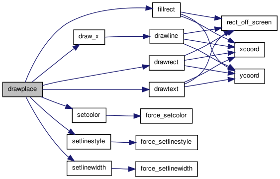 Here is the caller graph for this function:
| static void drawroute | ( | enum e_draw_net_type | draw_net_type | ) | [static] |
Draws the nets in the positions fixed by the router. If draw_net_type is ALL_NETS, draw all the nets. If it is HIGHLIGHTED, draw only the nets that are not coloured black (useful for drawing over the rr_graph). Next free track in each channel segment if routing is GLOBAL.
Definition at line 1748 of file draw.c.
{

    static int **chanx_track = NULL;    /* [1..nx][0..ny] */
    static int **chany_track = NULL;    /* [0..nx][1..ny] */

    int inet, i, j, inode, prev_node, prev_track, itrack;
    short switch_type;
    struct s_trace *tptr;
    t_rr_type rr_type, prev_type;


    if(draw_route_type == GLOBAL)
        {
            /* Allocate some temporary storage if it's not already available. */
            if(chanx_track == NULL)
                {
                    chanx_track =
                        (int **)alloc_matrix(1, nx, 0, ny, sizeof(int));
                }

            if(chany_track == NULL)
                {
                    chany_track =
                        (int **)alloc_matrix(0, nx, 1, ny, sizeof(int));
                }

            for(i = 1; i <= nx; i++)
                for(j = 0; j <= ny; j++)
                    chanx_track[i][j] = (-1);

            for(i = 0; i <= nx; i++)
                for(j = 1; j <= ny; j++)
                    chany_track[i][j] = (-1);
        }

    setlinestyle(SOLID);

/* Now draw each net, one by one.      */

    for(inet = 0; inet < num_nets; inet++)
        {
            if(clb_net[inet].is_global) /* Don't draw global nets. */
                continue;

            if(trace_head[inet] == NULL)        /* No routing.  Skip.  (Allows me to draw */
                continue;       /* partially complete routes).            */

            if(draw_net_type == HIGHLIGHTED && net_color[inet] == BLACK)
                continue;

            setcolor(net_color[inet]);
            tptr = trace_head[inet];    /* SOURCE to start */
            inode = tptr->index;
            rr_type = rr_node[inode].type;


            for(;;)
                {
                    prev_node = inode;
                    prev_type = rr_type;
                    switch_type = tptr->iswitch;
                    tptr = tptr->next;
                    inode = tptr->index;
                    rr_type = rr_node[inode].type;

                    switch (rr_type)
                        {

                        case OPIN:
                            draw_rr_pin(inode, net_color[inet]);
                            break;

                        case IPIN:
                            draw_rr_pin(inode, net_color[inet]);
                            prev_track =
                                get_track_num(prev_node, chanx_track,
                                              chany_track);
                            draw_pin_to_chan_edge(inode, prev_node);
                            break;

                        case CHANX:
                            if(draw_route_type == GLOBAL)
                                chanx_track[rr_node[inode].
                                            xlow][rr_node[inode].ylow]++;

                            itrack =
                                get_track_num(inode, chanx_track,
                                              chany_track);
                            draw_rr_chanx(inode, itrack);

                            switch (prev_type)
                                {

                                case CHANX:
                                    prev_track =
                                        get_track_num(prev_node, chanx_track,
                                                      chany_track);
                                    draw_chanx_to_chanx_edge(prev_node,
                                                             prev_track,
                                                             inode, itrack,
                                                             switch_type);
                                    break;

                                case CHANY:
                                    prev_track =
                                        get_track_num(prev_node, chanx_track,
                                                      chany_track);
                                    draw_chanx_to_chany_edge(inode, itrack,
                                                             prev_node,
                                                             prev_track,
                                                             FROM_Y_TO_X,
                                                             switch_type);
                                    break;

                                case OPIN:
                                    draw_pin_to_chan_edge(prev_node, inode);
                                    break;

                                default:
                                    printf
                                        ("Error in drawroute:  Unexpected connection from an \n"
                                         "rr_node of type %d to one of type %d.\n",
                                         prev_type, rr_type);
                                    exit(1);
                                }

                            break;

                        case CHANY:
                            if(draw_route_type == GLOBAL)
                                chany_track[rr_node[inode].
                                            xlow][rr_node[inode].ylow]++;

                            itrack =
                                get_track_num(inode, chanx_track,
                                              chany_track);
                            draw_rr_chany(inode, itrack);

                            switch (prev_type)
                                {

                                case CHANX:
                                    prev_track =
                                        get_track_num(prev_node, chanx_track,
                                                      chany_track);
                                    draw_chanx_to_chany_edge(prev_node,
                                                             prev_track,
                                                             inode, itrack,
                                                             FROM_X_TO_Y,
                                                             switch_type);
                                    break;

                                case CHANY:
                                    prev_track =
                                        get_track_num(prev_node, chanx_track,
                                                      chany_track);
                                    draw_chany_to_chany_edge(prev_node,
                                                             prev_track,
                                                             inode, itrack,
                                                             switch_type);
                                    break;

                                case OPIN:
                                    draw_pin_to_chan_edge(prev_node, inode);

                                    break;

                                default:
                                    printf
                                        ("Error in drawroute:  Unexpected connection from an \n"
                                         "rr_node of type %d to one of type %d.\n",
                                         prev_type, rr_type);
                                    exit(1);
                                }

                            break;

                        default:
                            break;

                        }

                    if(rr_type == SINK)
                        {       /* Skip the next segment */
                            tptr = tptr->next;
                            if(tptr == NULL)
                                break;
                            inode = tptr->index;
                            rr_type = rr_node[inode].type;
                        }

                }               /* End loop over traceback. */
        }                       /* End for (each net) */
}
Here is the call graph for this function: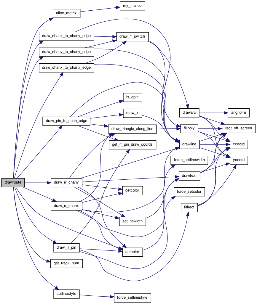 Here is the caller graph for this function:
| static void drawscreen | ( | ) | [static] |
This is the screen redrawing routine that event_loop assumes exists. It erases whatever is on screen, then calls redraw_screen to redraw it.
Definition at line 277 of file draw.c.
{

    clearscreen();
    redraw_screen();
}
Here is the call graph for this function: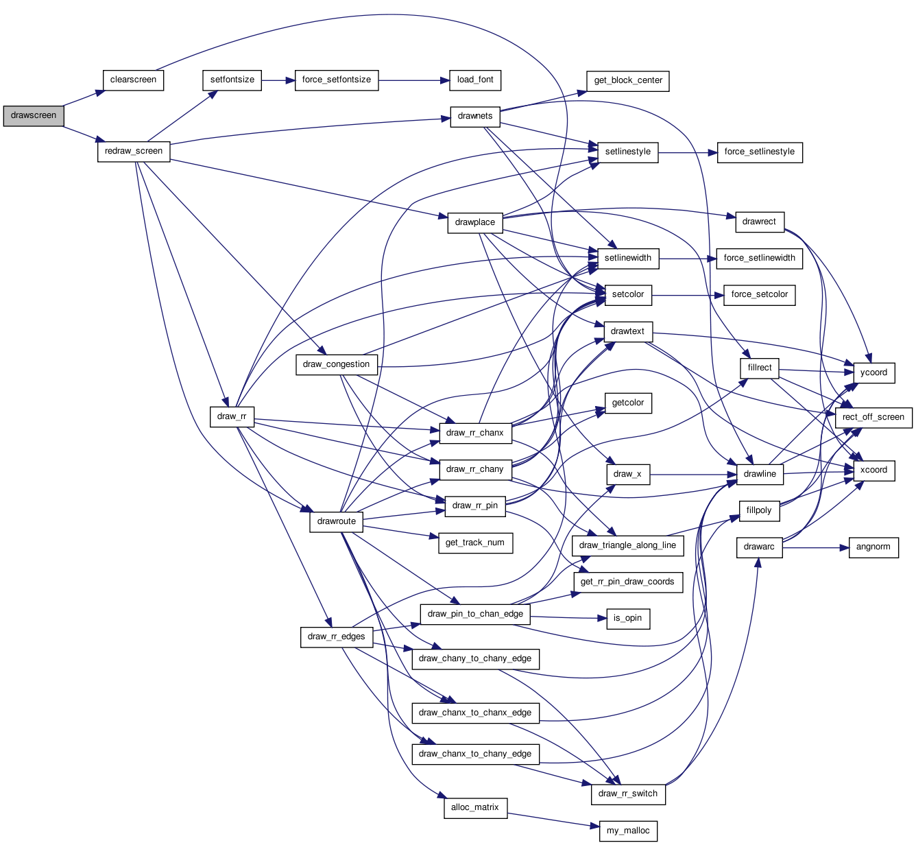 Here is the caller graph for this function:
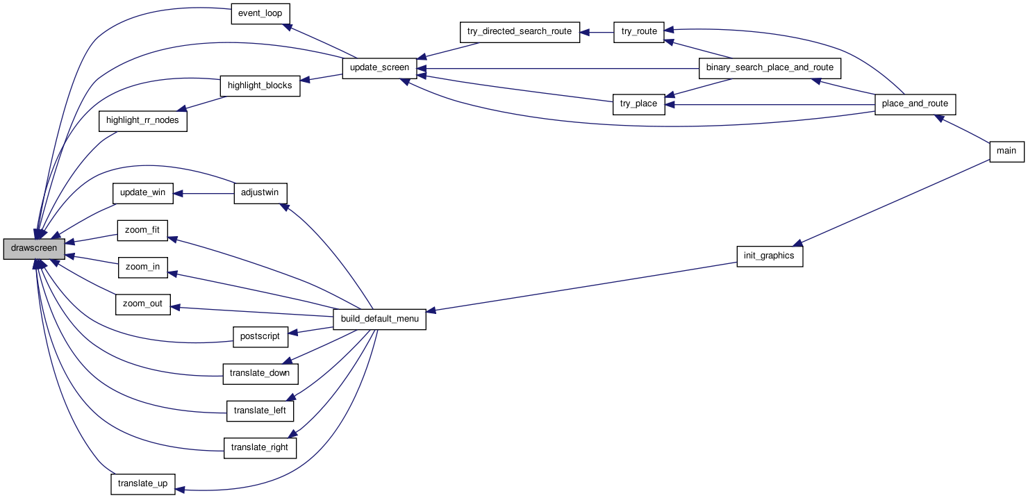
| static void get_block_center | ( | int | bnum, |
| float * | x, | ||
| float * | y | ||
| ) | [static] |
This routine finds the center of block bnum in the current placement, and returns it in *x and *y. This is used in routine shownets.
Definition at line 724 of file draw.c.
{

    int i, j, k;
    float sub_tile_step;

    i = block[bnum].x;
    j = block[bnum].y;
    k = block[bnum].z;

    sub_tile_step = tile_width / block[bnum].type->capacity;

    if((i < 1) || (i > nx))
        {                       /* Left and right fringe */
            *x = tile_x[i] + (sub_tile_step * (k + 0.5));
        }
    else
        {
            *x = tile_x[i] + (tile_width / 2.0);
        }

    if((j < 1) || (j > ny))
        {                       /* Top and bottom fringe */
            *y = tile_y[j] + (sub_tile_step * (k + 0.5));
        }
    else
        {
            *y = tile_y[j] + (tile_width / 2.0);
        }
}
Here is the caller graph for this function: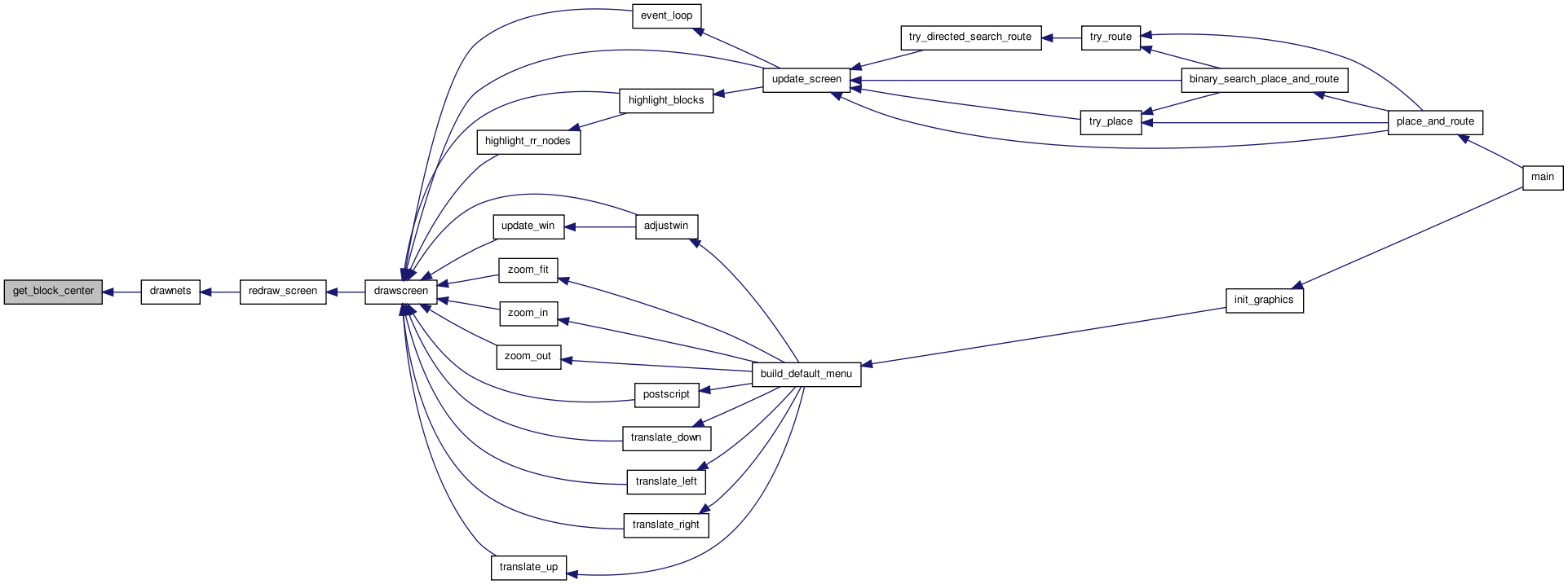
| static void get_rr_pin_draw_coords | ( | int | inode, |
| int | iside, | ||
| int | ioff, | ||
| float * | xcen, | ||
| float * | ycen | ||
| ) | [static] |
Returns the coordinates at which the center of this pin should be drawn. inode gives the node number, and iside gives the side of the clb or pad the physical pin is on.
Definition at line 1681 of file draw.c.
{

    int i, j, k, ipin, pins_per_sub_tile;
    float offset, xc, yc, step;
    t_type_ptr type;

    i = rr_node[inode].xlow;
    j = rr_node[inode].ylow + ioff;     /* Need correct tile of block */

    xc = tile_x[i];
    yc = tile_y[j];

    ipin = rr_node[inode].ptc_num;
    type = grid[i][j].type;
    pins_per_sub_tile = grid[i][j].type->num_pins / grid[i][j].type->capacity;
    k = ipin / pins_per_sub_tile;

    /* Since pins numbers go across all sub_tiles in a block in order
     * we can treat as a block box for this step */

    /* For each sub_tile we need and extra padding space */
    step = (float)(tile_width) / (float)(type->num_pins + type->capacity);
    offset = (ipin + k + 1) * step;

    switch (iside)
        {
        case LEFT:
            yc += offset;
            break;

        case RIGHT:
            xc += tile_width;
            yc += offset;
            break;

        case BOTTOM:
            xc += offset;
            break;

        case TOP:
            xc += offset;
            yc += tile_width;
            break;

        default:
            printf("Error in get_rr_pin_draw_coords:  Unexpected iside %d.\n",
                   iside);
            exit(1);
            break;
        }

    *xcen = xc;
    *ycen = yc;
}
Here is the caller graph for this function: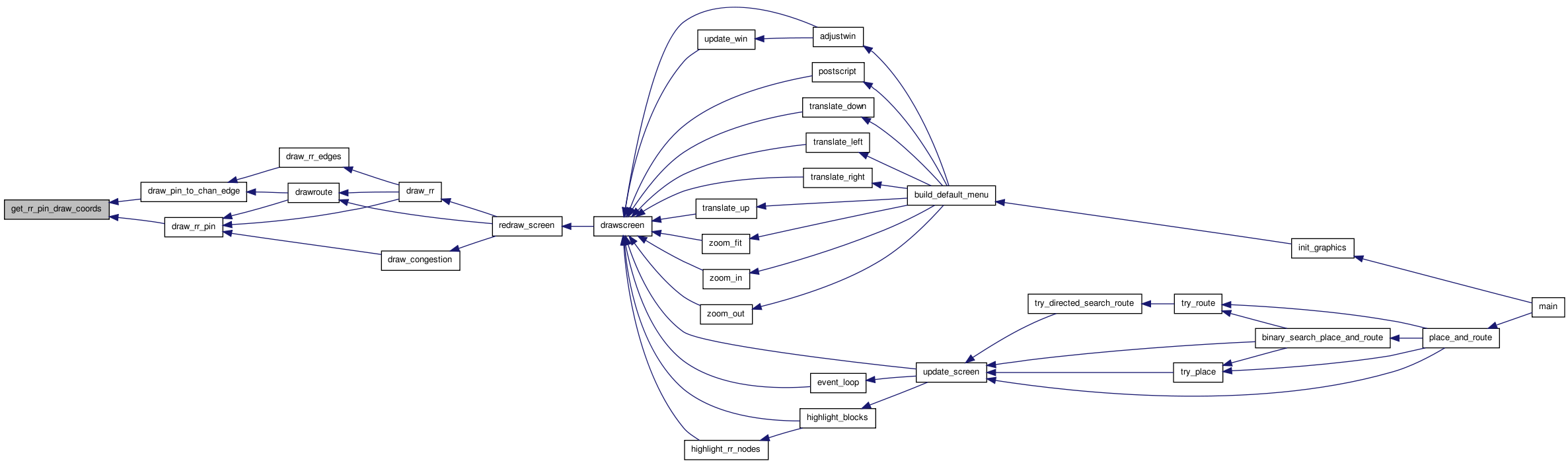
| static int get_track_num | ( | int | inode, |
| int ** | chanx_track, | ||
| int ** | chany_track | ||
| ) | [static] |
Returns the track number of this routing resource node.
Definition at line 1947 of file draw.c.
{
    int i, j;
    t_rr_type rr_type;

    if(draw_route_type == DETAILED)
        return (rr_node[inode].ptc_num);

/* GLOBAL route stuff below. */

    rr_type = rr_node[inode].type;
    i = rr_node[inode].xlow;    /* NB: Global rr graphs must have only unit */
    j = rr_node[inode].ylow;    /* length channel segments.                 */

    switch (rr_type)
        {
        case CHANX:
            return (chanx_track[i][j]);

        case CHANY:
            return (chany_track[i][j]);

        default:
            printf
                ("Error in get_track_num:  unexpected node type %d for node %d."
                 "\n", rr_type, inode);
            exit(1);
        }
}
Here is the caller graph for this function: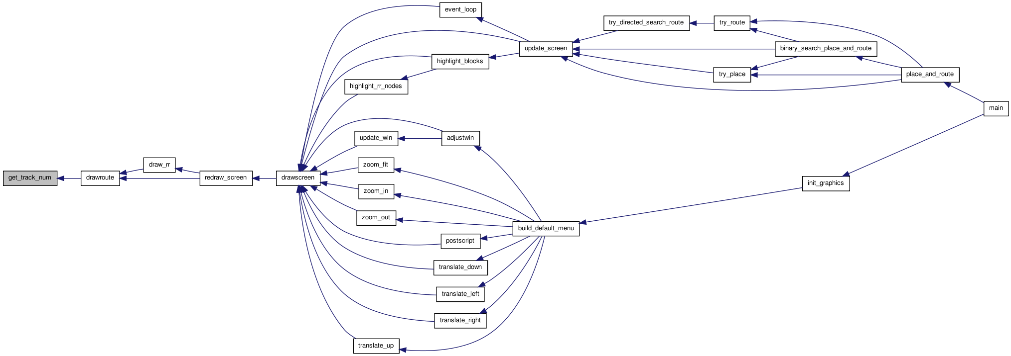
| static void highlight_blocks | ( | float | x, |
| float | y | ||
| ) | [static] |
This routine is called when the user clicks in the graphics area. It determines if a clb was clicked on. If one was, it is highlighted in green, it's fanin nets and clbs are highlighted in blue and it's fanout is highlighted in red. If no clb was clicked on (user clicked on white space) any old highlighting is removed. Note that even though global nets are not drawn, their fanins and fanouts are highlighted when you click on a block attached to them.
Definition at line 2080 of file draw.c.
{
    int i, j, k, hit, bnum, ipin, netnum, fanblk;
    int iclass;
    float io_step;
    t_type_ptr type;
    char msg[BUFSIZE];

    deselect_all();

    hit = i = j = k = 0;

    for(i = 0; i <= (nx + 1) && !hit; i++)
        {
            if(x <= tile_x[i] + tile_width)
                {
                        if(x >= tile_x[i]){
                            for(j = 0; j <= (ny + 1) && !hit; j++)
                                {
                                        if(grid[i][j].offset != 0)
                                                continue;
                                        type = grid[i][j].type;
                                        if(y <= tile_y[j + type->height - 1] + tile_width)
                                        {
                                                if(y >= tile_y[j])
                                                        hit = 1;
                                        }
                                }

                        }
                }
        }
        i--;
        j--;

    if(!hit)
        {
            highlight_rr_nodes(x, y);
            /* update_message(default_message);
               drawscreen(); */
            return;
        }
    type = grid[i][j].type;
    hit = 0;

    if(EMPTY_TYPE == type)
        {
            update_message(default_message);
            drawscreen();
            return;
        }

    /* The user selected the clb at location (i,j). */
    io_step = tile_width / type->capacity;

    if((i < 1) || (i > nx))     /* Vertical columns of IOs */
        k = (int)((y - tile_y[j]) / io_step);
    else
        k = (int)((x - tile_x[i]) / io_step);

    assert(k < type->capacity);
    if(grid[i][j].blocks[k] == EMPTY)
        {
            update_message(default_message);
            drawscreen();
            return;
        }
    bnum = grid[i][j].blocks[k];

    /* Highlight fanin and fanout. */

    for(k = 0; k < type->num_pins; k++)
        {                       /* Each pin on a CLB */
            netnum = block[bnum].nets[k];

            if(netnum == OPEN)
                continue;

            iclass = type->pin_class[k];

            if(type->class_inf[iclass].type == DRIVER)
                {               /* Fanout */
                    net_color[netnum] = RED;
                    for(ipin = 1; ipin <= clb_net[netnum].num_sinks; ipin++)
                        {
                            fanblk = clb_net[netnum].node_block[ipin];
                            block_color[fanblk] = RED;
                        }
                }
            else
                {               /* This net is fanin to the block. */
                    net_color[netnum] = BLUE;
                    fanblk = clb_net[netnum].node_block[0];     /* DRIVER to net */
                    block_color[fanblk] = BLUE;
                }
        }

    block_color[bnum] = GREEN;  /* Selected block. */

    sprintf(msg, "Block %d (%s) at (%d, %d) selected.", bnum,
            block[bnum].name, i, j);
    update_message(msg);
    drawscreen();               /* Need to erase screen. */
}
Here is the call graph for this function: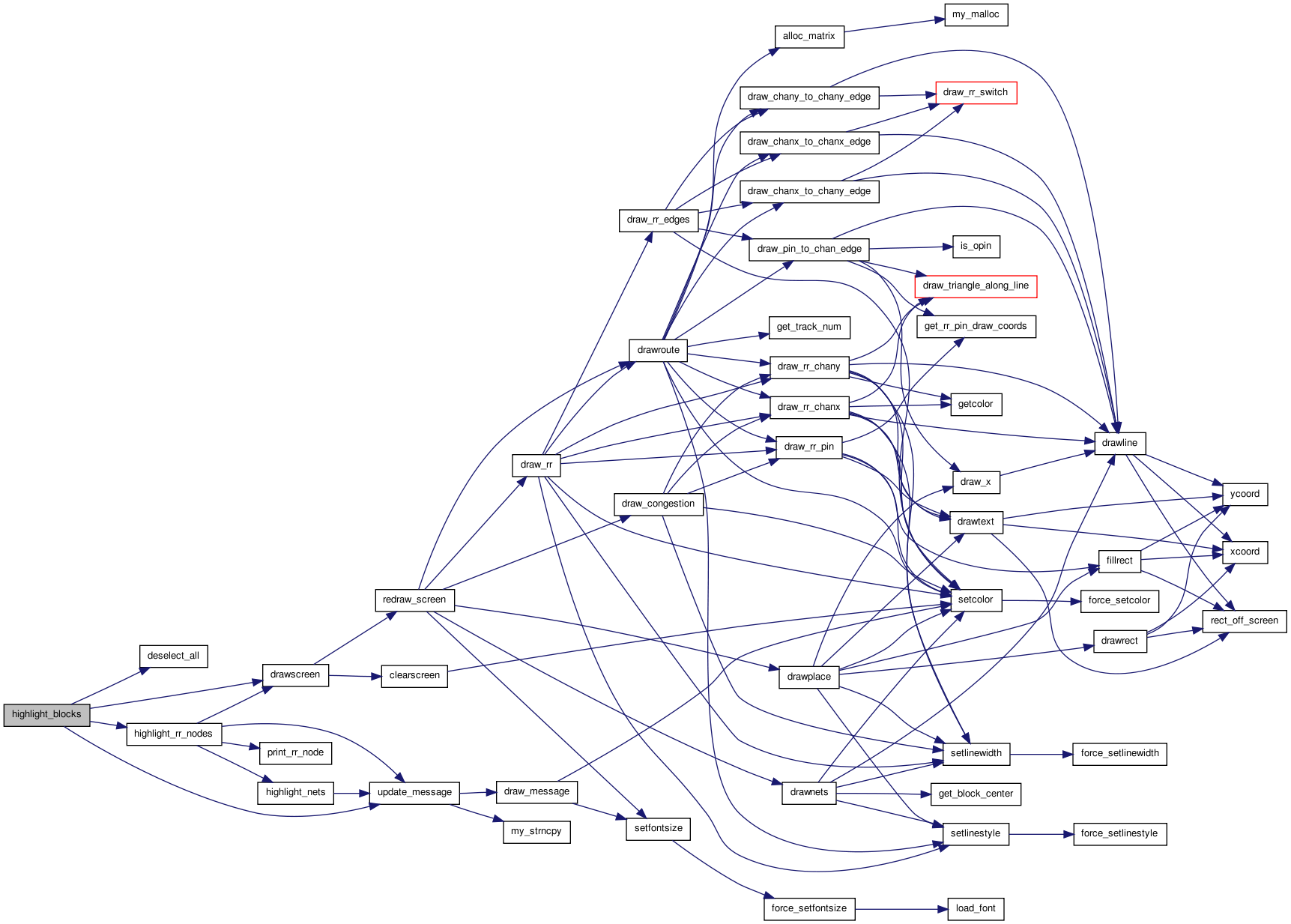 Here is the caller graph for this function:
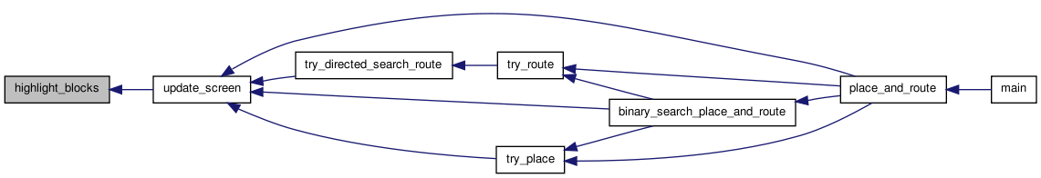
| static void highlight_crit_path | ( | void(*)(void) | drawscreen_ptr | ) | [static] |
Highlights all the blocks and nets on the critical path.
Definition at line 403 of file draw.c.
{
    t_linked_int *critical_path_head, *critical_path_node;
    int inode, iblk, inet, num_nets_seen;
    static int nets_to_highlight = 1;
    char msg[BUFSIZE];

    if(nets_to_highlight == 0)
        {                       /* Clear the display of all highlighting. */
            nets_to_highlight = 1;
            deselect_all();
            update_message(default_message);
            drawscreen_ptr();
            return;
        }

    critical_path_head = allocate_and_load_critical_path();
    critical_path_node = critical_path_head;
    num_nets_seen = 0;

    while(critical_path_node != NULL)
        {
            inode = critical_path_node->data;
            get_tnode_block_and_output_net(inode, &iblk, &inet);

            if(num_nets_seen == nets_to_highlight)
                {               /* Last block */
                    block_color[iblk] = MAGENTA;
                }
            else if(num_nets_seen == nets_to_highlight - 1)
                {               /* 2nd last block */
                    block_color[iblk] = YELLOW;
                }
            else if(num_nets_seen < nets_to_highlight)
                {               /* Earlier block */
                    block_color[iblk] = DARKGREEN;
                }

            if(inet != OPEN)
                {
                    num_nets_seen++;

                    if(num_nets_seen < nets_to_highlight)
                        {       /* First nets. */
                            net_color[inet] = DARKGREEN;
                        }
                    else if(num_nets_seen == nets_to_highlight)
                        {
                            net_color[inet] = CYAN;     /* Last (new) net. */
                        }
                }

            critical_path_node = critical_path_node->next;
        }

    if(nets_to_highlight == num_nets_seen)
        {
            nets_to_highlight = 0;
            sprintf(msg, "All %d nets on the critical path highlighted.",
                    num_nets_seen);
        }
    else
        {
            sprintf(msg, "First %d nets on the critical path highlighted.",
                    nets_to_highlight);
            nets_to_highlight++;
        }

    free_int_list(&critical_path_head);

    update_message(msg);
    drawscreen_ptr();
}
Here is the call graph for this function: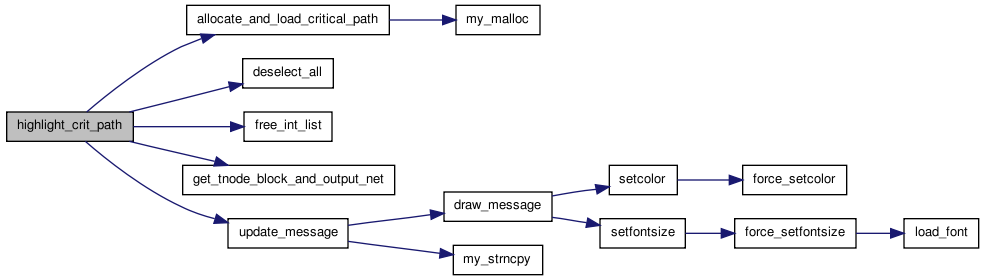 Here is the caller graph for this function:
| static void highlight_nets | ( | char * | message | ) | [static] |
Definition at line 1980 of file draw.c.
{
    int inet;
    struct s_trace *tptr;

    for(inet = 0; inet < num_nets; inet++)
    {
            for(tptr = trace_head[inet]; tptr != NULL; tptr = tptr->next)
            {
                    if(rr_node_color[tptr->index] != BLACK)
                    {
                            net_color[inet] = rr_node_color[tptr->index];
                            sprintf(message, "%s  ||  Net:%d %d", message,inet,
                                            trace_head[inet]->index
                                   );
                            break;
                    }
            }
    }
    update_message (message);
}
Here is the call graph for this function: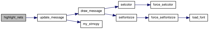 Here is the caller graph for this function:
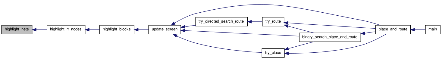
| static void highlight_rr_nodes | ( | float | x, |
| float | y | ||
| ) | [static] |
Definition at line 2003 of file draw.c.
{
    int inode;
    int hit = 0;
    char message[250] = "";
    int edge;

    if(draw_rr_toggle == DRAW_NO_RR && ! show_nets)
    {
        update_message(default_message);
        drawscreen();
        return;
    }

    for(inode = 0; inode < num_rr_nodes; inode++)
    {
        if(x >= x_rr_node_left[inode] &&
                x <= x_rr_node_right[inode] &&
                y >= y_rr_node_bottom[inode] &&
                y <= y_rr_node_top[inode])
        {
            t_rr_type rr_type = rr_node[inode].type;
            int xlow = rr_node[inode].xlow;
            int xhigh = rr_node[inode].xhigh;
            int ylow = rr_node[inode].ylow;
            int yhigh = rr_node[inode].yhigh;
            int ptc_num = rr_node[inode].ptc_num;
            rr_node_color[inode] = MAGENTA;
            sprintf(message, "%s%s %d: %s (%d,%d) -> (%d,%d) track: %d", message,
                    (hit?"   |   ":""), inode, name_type[rr_type], xlow,ylow
                    , xhigh, yhigh, ptc_num
                   );

#ifdef DEBUG
            print_rr_node(stdout, rr_node, inode);
#endif
            for(edge = 0; edge < rr_node[inode].num_edges; edge++)
            {
                if(rr_node_color[rr_node[inode].edges[edge]] == BLACK &&
                        rr_node[rr_node[inode].edges[edge]].capacity >
                        rr_node[rr_node[inode].edges[edge]].occ)
                    rr_node_color[rr_node[inode].edges[edge]] = GREEN;
                else if(rr_node_color[rr_node[inode].edges[edge]] == BLACK &&
                        rr_node[rr_node[inode].edges[edge]].capacity ==
                        rr_node[rr_node[inode].edges[edge]].occ)
                    rr_node_color[rr_node[inode].edges[edge]] = BLUE;

            }
            hit = 1;
        }
    }


    if (!hit) {
        update_message(default_message);
        drawscreen();
        return;
    }

    if(show_nets)
    {
        highlight_nets(message);
    }else
        update_message(message);
    drawscreen();
}
Here is the call graph for this function: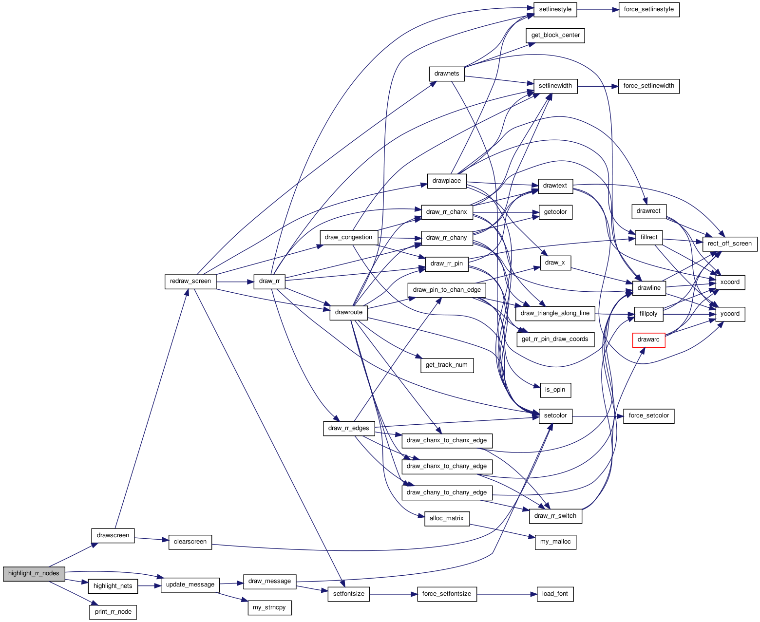 Here is the caller graph for this function:
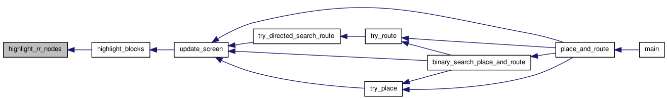
| void init_draw_coords | ( | float | width_val | ) |
Load the arrays containing the left and bottom coordinates of the clbs forming the FPGA. tile_width_val sets the width and height of a drawn clb.
Definition at line 508 of file draw.c.
{
    int i;
    int j;

    if(!show_graphics)
        return;                 /* -nodisp was selected. */

    if(num_rr_nodes != old_num_rr_nodes)
    {
        x_rr_node_left = (float *) my_realloc(x_rr_node_left, (num_rr_nodes)*sizeof(float));
        x_rr_node_right = (float *) my_realloc(x_rr_node_right, (num_rr_nodes)*sizeof(float));
        y_rr_node_top = (float *) my_realloc(y_rr_node_top, (num_rr_nodes)*sizeof(float));
        y_rr_node_bottom = (float *) my_realloc(y_rr_node_bottom, (num_rr_nodes)*sizeof(float));
        rr_node_color = (enum color_types *) my_realloc(rr_node_color, (num_rr_nodes)*sizeof(enum color_types));
        for (i = 0; i < num_rr_nodes; i++)
        {
                x_rr_node_left[i] = -1;
                x_rr_node_right[i] = -1;
                y_rr_node_top[i] = -1;
                y_rr_node_bottom[i] = -1;
                rr_node_color[i] = BLACK;
        }
    }


    tile_width = width_val;
    pin_size = 0.3;
    for(i = 0; i < num_types; ++i)
        {
            pin_size =
                min(pin_size,
                    (tile_width / (4.0 * type_descriptors[i].num_pins)));
        }

    j = 0;
    for(i = 0; i < (nx + 1); i++)
        {
            tile_x[i] = (i * tile_width) + j;
            j += chan_width_y[i] + 1;   /* N wires need N+1 units of space */
        }
    tile_x[nx + 1] = ((nx + 1) * tile_width) + j;

    j = 0;
    for(i = 0; i < (ny + 1); ++i)
        {
            tile_y[i] = (i * tile_width) + j;
            j += chan_width_x[i] + 1;
        }
    tile_y[ny + 1] = ((ny + 1) * tile_width) + j;

    init_world(0.0,
               tile_y[ny + 1] + tile_width, tile_x[nx + 1] + tile_width, 0.0);
}
Here is the call graph for this function: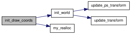 Here is the caller graph for this function:
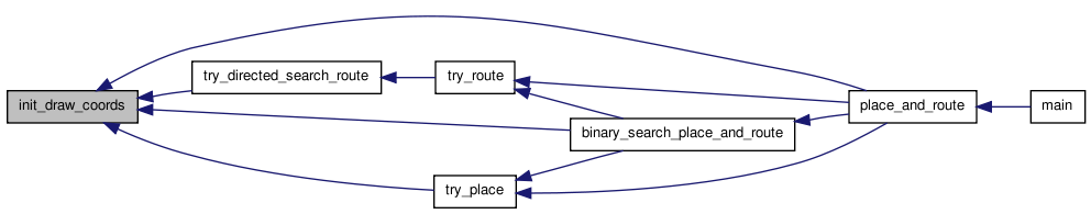
| static void redraw_screen | ( | ) | [static] |
The screen redrawing routine called by drawscreen and highlight_blocks. Call this routine instead of drawscreen if you know you don't need to erase the current graphics, and want to avoid a screen "flash".
Definition at line 291 of file draw.c.
{

    setfontsize(14);            /* UDSD Modification by WMF */
    if(pic_on_screen == PLACEMENT)
        {
            drawplace();
            if(show_nets)
                {
                    drawnets();
                }
        }
    else
        {                       /* ROUTING on screen */
            drawplace();

            if(show_nets)
                {
                    drawroute(ALL_NETS);
                }
            else
                {
                    draw_rr();
                }

            if(show_congestion)
                {
                    draw_congestion();
                }
        }
}
Here is the call graph for this function: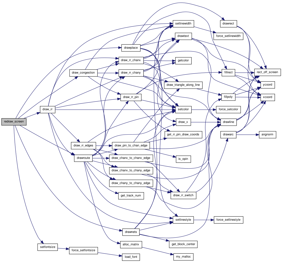 Here is the caller graph for this function:
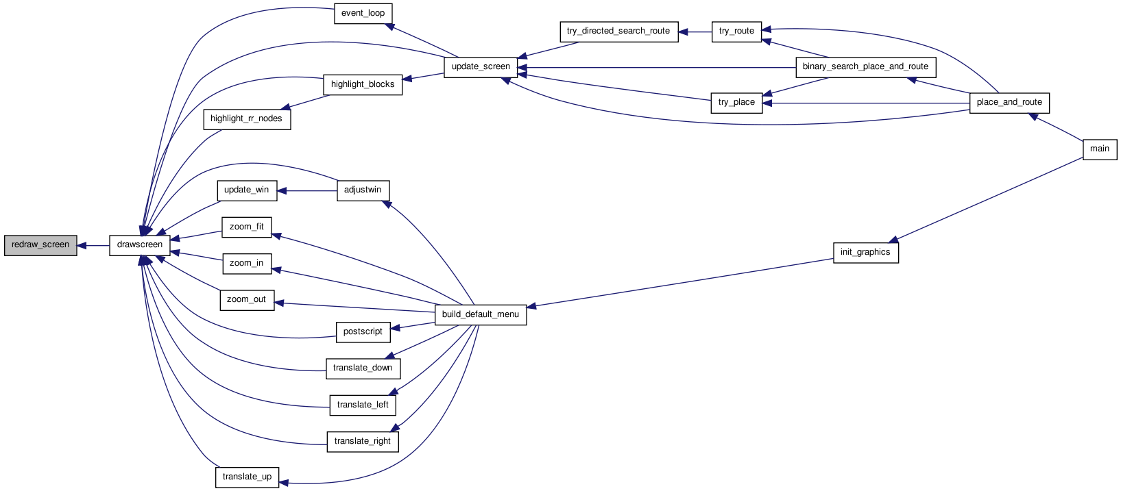
| void set_graphics_state | ( | boolean | show_graphics_val, |
| int | gr_automode_val, | ||
| enum e_route_type | route_type | ||
| ) |
Sets the static show_graphics and gr_automode variables to the desired values. They control if graphics are enabled and, if so, how often the user is prompted for input.
Definition at line 182 of file draw.c.
{
    show_graphics = show_graphics_val;
    gr_automode = gr_automode_val;
    draw_route_type = route_type;
}
Here is the caller graph for this function: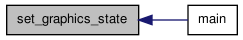
| static void toggle_congestion | ( | void(*)(void) | drawscreen_ptr | ) | [static] |
Turns the congestion display on and off.
Definition at line 369 of file draw.c.
{
    char msg[BUFSIZE];
    int inode, num_congested;

    show_nets = FALSE;
    draw_rr_toggle = DRAW_NO_RR;
    show_congestion = !show_congestion;

    if(!show_congestion)
        {
            update_message(default_message);
        }
    else
        {
            num_congested = 0;
            for(inode = 0; inode < num_rr_nodes; inode++)
                {
                    if(rr_node[inode].occ > rr_node[inode].capacity)
                        {
                            num_congested++;
                        }
                }

            sprintf(msg, "%d routing resources are overused.", num_congested);
            update_message(msg);
        }

    drawscreen_ptr();
}
Here is the call graph for this function: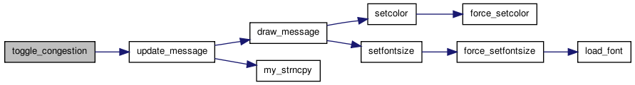 Here is the caller graph for this function:
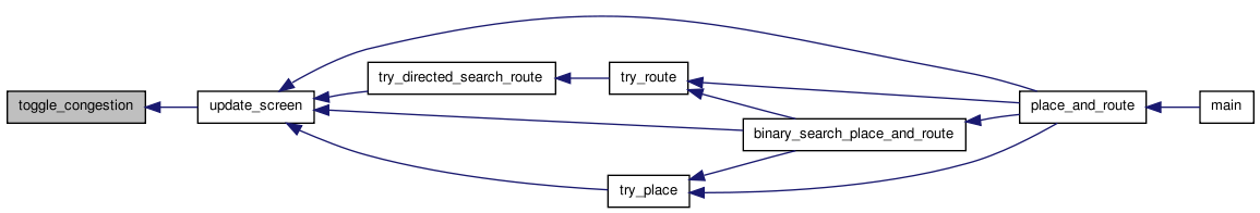
| static void toggle_defects | ( | void(*)(void) | drawscreen | ) | [static] |
Definition at line 359 of file draw.c.
{
    show_defects = !show_defects;
    update_message(default_message);
    drawscreen_ptr();
}
Here is the call graph for this function: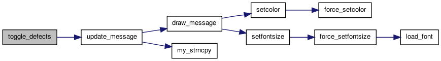 Here is the caller graph for this function:
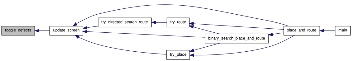
| static void toggle_nets | ( | void(*)(void) | drawscreen_ptr | ) | [static] |
Enables/disables drawing of nets when a the user clicks on a button. Also disables drawing of routing resources. See graphics.c for details of how buttons work.
Definition at line 329 of file draw.c.
{
    show_nets = !show_nets;
    draw_rr_toggle = DRAW_NO_RR;
    show_congestion = FALSE;

    update_message(default_message);
    drawscreen_ptr();
}
Here is the call graph for this function: Here is the caller graph for this function:
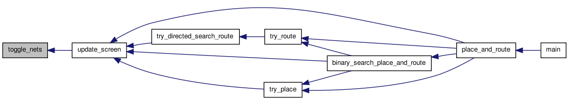
| static void toggle_rr | ( | void(*)(void) | drawscreen_ptr | ) | [static] |
Cycles through the options for viewing the routing resources available in an FPGA. If a routing isn't on screen, the routing graph hasn't been built, and this routine doesn't switch the view. Otherwise, this routine switches to the routing resource view. Clicking on the toggle cycles through the options: DRAW_NO_RR, DRAW_ALL_RR, DRAW_ALL_BUT_BUFFERS_RR, DRAW_NODES_AND_SBOX_RR, and DRAW_NODES_RR.
Definition at line 348 of file draw.c.
{
    draw_rr_toggle = (draw_rr_toggle + 1) % (DRAW_RR_TOGGLE_MAX);
    show_nets = FALSE;
    show_congestion = FALSE;

    update_message(default_message);
    drawscreen_ptr();
}
Here is the call graph for this function: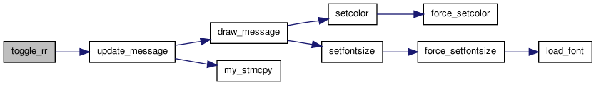 Here is the caller graph for this function:
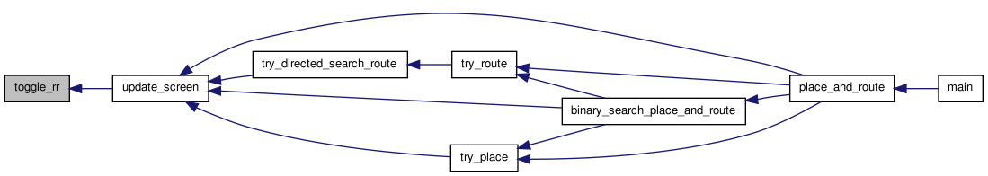
| void update_screen | ( | int | priority, |
| char * | msg, | ||
| enum pic_type | pic_on_screen_val, | ||
| boolean | crit_path_button_enabled | ||
| ) |
Updates the screen if the user has requested graphics. The priority value controls whether or not the Proceed button must be clicked to continue. Saves the pic_on_screen_val to allow pan and zoom redraws.
Definition at line 197 of file draw.c.
{
    if(!show_graphics)          /* Graphics turned off */
        return;

    /* If it's the type of picture displayed has changed, set up the proper  *
     * buttons.                                                              */
    if(pic_on_screen != pic_on_screen_val)
        {
            if(pic_on_screen_val == PLACEMENT && pic_on_screen == NO_PICTURE)
                {
                    create_button("Window", "Toggle Nets", toggle_nets);
                }
            else if(pic_on_screen_val == ROUTING
                    && pic_on_screen == PLACEMENT)
                {
                    create_button("Toggle Nets", "Toggle RR", toggle_rr);
                    create_button("Toggle RR", "Tog Defects", toggle_defects);
                    create_button("Toggle RR", "Congestion",
                                  toggle_congestion);

                    if(crit_path_button_enabled)
                        {
                            create_button("Congestion", "Crit. Path",
                                          highlight_crit_path);
                        }
                }
            else if(pic_on_screen_val == PLACEMENT
                    && pic_on_screen == ROUTING)
                {
                    destroy_button("Toggle RR");
                    destroy_button("Congestion");

                    if(crit_path_button_enabled)
                        {
                            destroy_button("Crit. Path");
                        }
                }
            else if(pic_on_screen_val == ROUTING
                    && pic_on_screen == NO_PICTURE)
                {
                    create_button("Window", "Toggle Nets", toggle_nets);
                    create_button("Toggle Nets", "Toggle RR", toggle_rr);
                    create_button("Toggle RR", "Tog Defects", toggle_defects);
                    create_button("Tog Defects", "Congestion",
                                  toggle_congestion);

                    if(crit_path_button_enabled)
                        {
                            create_button("Congestion", "Crit. Path",
                                          highlight_crit_path);
                        }
                }
        }
    /* Save the main message. */

    my_strncpy(default_message, msg, BUFSIZE);

    pic_on_screen = pic_on_screen_val;
    update_message(msg);
    drawscreen();
    if(priority >= gr_automode)
        {
            event_loop(highlight_blocks, drawscreen);
        }
    else
        {
            flushinput();
        }
}
Here is the call graph for this function: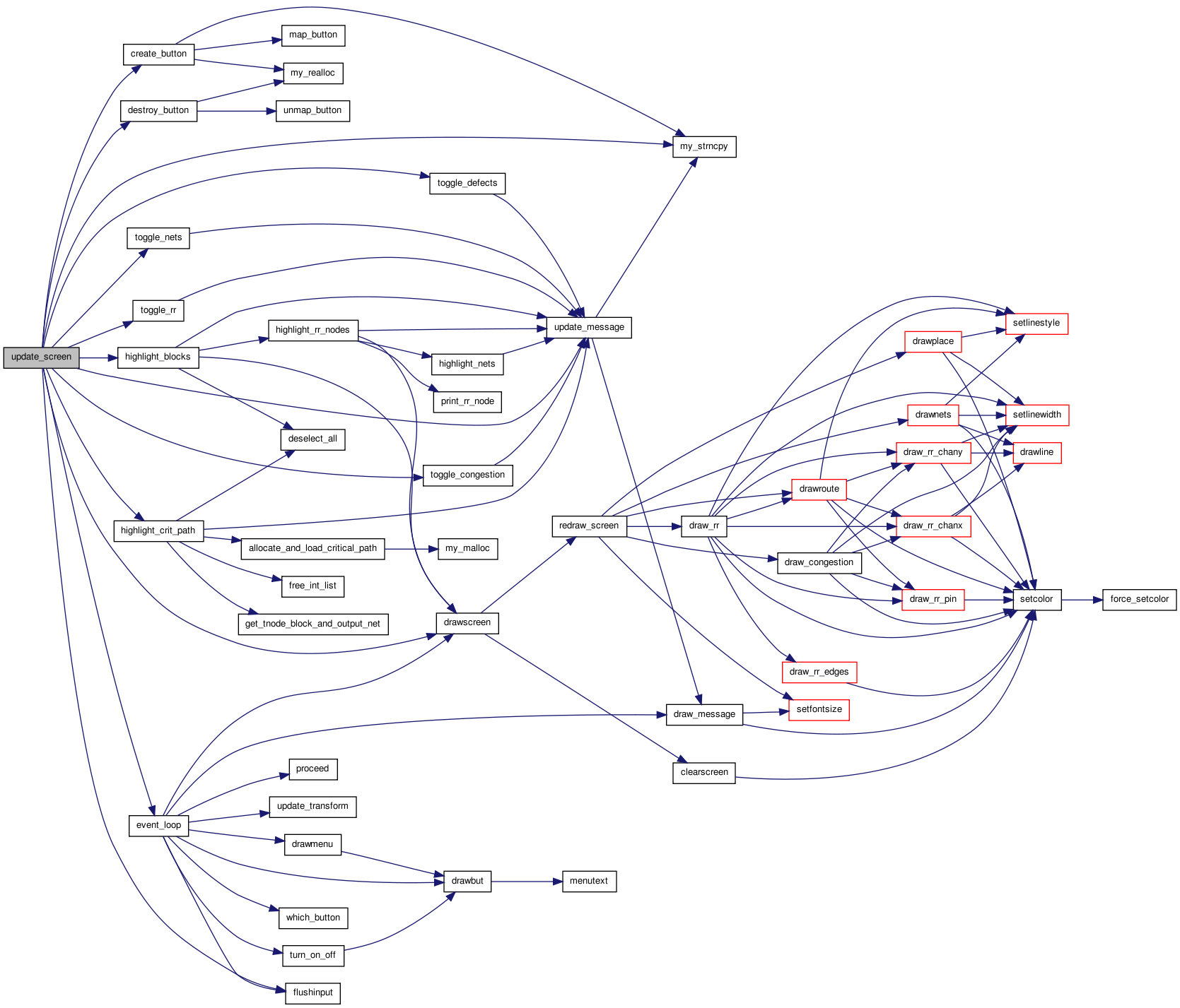 Here is the caller graph for this function:
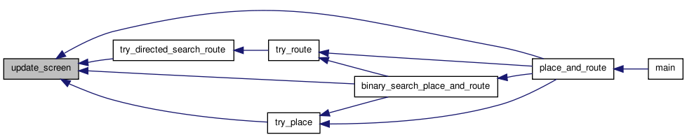
Variable Documentation
| enum color_types * block_color |
char default_message[BUFSIZE] [static] |
enum e_route_type draw_route_type [static] |
enum e_draw_rr_toggle draw_rr_toggle = DRAW_NO_RR [static] |
int gr_automode [static] |
char* name_type[] [static] |
enum color_types* net_color [static] |
int old_num_rr_nodes = 0 [static] |
enum pic_type pic_on_screen = NO_PICTURE [static] |
enum color_types* rr_node_color = NULL [static] |
boolean show_congestion = FALSE [static] |
boolean show_defects = FALSE [static] |
boolean show_graphics [static] |
float tile_width [static] |
float* tile_x [static] |
float* x_rr_node_left = NULL [static] |
float* x_rr_node_right = NULL [static] |
float* y_rr_node_bottom = NULL [static] |
float* y_rr_node_top = NULL [static] |