Print version of this Book (PDF file)
Gate Charge Model
The Agilent EEHEMT1 gate charge model was developed through careful examination of extracted device capacitances over bias. The model consists of simple closed form charge expressions whose derivatives fit observed bias dependencies in capacitance data. This capacitance data can be obtained directly from measured Y-parameter data:
The capacitance data is remarkably self-consistent. In other words, a single qg function's derivatives will fit both C11 data and C12 data. The Agilent EEHEMT1 gate charge expression is:
This expression is valid for both positive and negative Vds. Symmetry is forced through the following smoothing functions proposed by Statz [4]:
Differentiating the gate charge expression wrt Vgs yields the following expression for the gate capacitance C11:
The gate transcapacitance C12 is defined as:
The Agilent EEHEMT1 topology requires that the gate charge be subdivided between the respective charge sources qgc and qgy. Although simulation could be performed directly from the nodal gate charge qg, division of the charge into branches permits the inclusion of the resistances RIS and RID that model charging delay between the depletion region and the channel. Agilent EEHEMT1 assumes the following form for the gate-drain charge in saturation:
which gives rise to a constant gate-drain capacitance in saturation.
The gate-source charge qgc can now be obtained by subtracting the latter from the gate charge equation. Smoothing functions can then be applied to these expressions in saturation in order to extend the model's applicable bias range to all Vds values. These smoothing functions force symmetry on the qgy and qgc charges such that
at Vgc = Vgy. Under large negative Vds (saturation at the source end of the device), qgy and qgc swap roles, i.e:
The following continuous charge equations satisfy these constraints and are specified in terms of the gate charge:
where f1 and f2 are smoothing functions defined by
The capacitances associated with these branch charge sources can be obtained through differentiation of the qgc and qgy equations and by application of the chain rule to the capacitances C11 and C12. The gate charge derivatives re-formulated in terms of Vgc and Vgy are:
The branch charge derivatives are:
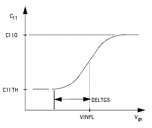
When Vds=VDSO and VDSO>>DELTDS, the gate capacitance C11 reduces to a single voltage dependency in Vgs. Similar to the Ids model, the majority of the important gate charge parameters can then be estimated from a single trace of a plot. In this case, the plot of interest is C11-Vgs at Vds = VDSO. The parameter definitions are illustrated in the following figure.
The parameter DELTDS models the gate capacitance transition from the linear region of the device into saturation. LAMBDA models the slope of the C11-Vds characteristic in saturation. C12SAT is used to fit the gate transcapacitance (C12) in saturation.


