Print version of this Book (PDF file)
Drain-Source Current
The drain-source current model in Agilent EEHEMT1 is comprised of various analytic expressions that were developed through examination of gm vs. bias plots on a wide class of devices from various manufacturers. The expressions below are given for Vds > 0.0 V although the model is equally valid for Vds < 0.0 V. The model assumes the device is symmetrical, and one need only replace Vgs with Vgd and Vds with -Vds in order to obtain the reverse region (Vds < 0.0 V) equations. The gm, gds and Ids equations take on 4 different forms depending on the value of Vgs relative to some of the model parameters. The Ids expression is continuous through at least the second derivative everywhere.
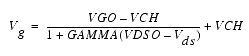
 Vg
Vg
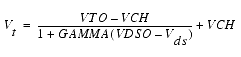
 Vt
Vt
The following voltages define regions of operation that are used in the gm compression terms:
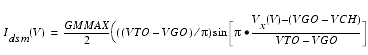
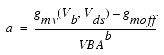
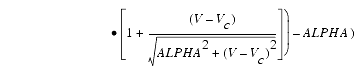
For Vgs > Vc, the basic Idso, gmo and gdso relations are modified as follows:
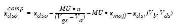
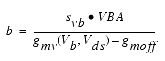
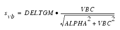
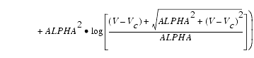

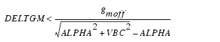
In order to prevent gm from becoming negative at high gate-source biases, the following restriction is placed on the parameter DELTGM:
The preceding relations for ![]() ,
, ![]() and
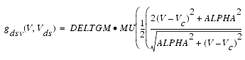
and ![]() can now be substituted in the following equations that model the current saturation and output conductance. This portion of the model can be recognized from the work of Curtice [1].
can now be substituted in the following equations that model the current saturation and output conductance. This portion of the model can be recognized from the work of Curtice [1].
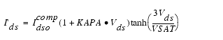
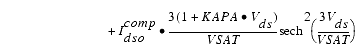
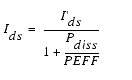
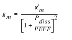
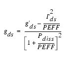
These expressions do an excellent job of fitting HEMT I-V characteristics in regions of low power dissipation. They will also fit pulsed (isothermal) I-V characteristics. In order to model negative conductance effects due to self-heating, the thermal model of Canfield was incorporated [2]. With this final enhancement, the DC expressions for Ids and its associated conductances become:
Qualitatively, the operation of the drain-source model can be described as follows:
The Vds dependence of the equations is dominated by the parameters VSAT, GAMMA, KAPA, and PEFF. Isothermal output conductance is controlled by GAMMA and KAPA. The impact of GAMMA on output conductance is more significant near threshold. At Vgs=VCH, the output conductance is controlled only by KAPA. The parameter PEFF provides a correction to the isothermal model for modeling the self-heating effects manifested as a negative resistance on the I-V curves. The parameter VSAT represents the drain-source voltage at which the current saturates and output conductance becomes a constant (approximately). The parameter MU also impacts the I-V curves in the gm compression region, but its effect is second order. In most cases, the gm fit is more sensitive to the parameter MU.
The overall impact of VCH on the I-V characteristics is second order at best, and many different values of VCH will provide good fits to I-V plots. For most applications encountered, it is our experience that the default value of 1.0V is an adequate value for VCH. Similar to VCH, VDSO is a parameter that should be set rather than optimized. At Vds = VDSO, the drain-source model collapses to a single voltage dependency in Vgs. It is recommended that the user set VDSO to a typical Vds operating point in saturation. At this point, many of the parameters
can be extracted right off a Ids-Vgs plot for Vds=VDSO or, preferably, a gm(DC)-Vgs plot at Vds=VDSO.
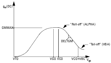
When Vds=VDSO and PEFF is set large (to disable the self-heating model), the significance of the parameters VTO, VGO, GMMAX, VCO, VBA, VBC, DELTGM and ALPHA are easily understood from a plot of gm(DC)-Vgs. GMMAX is the peak transconductance of the model that occurs at Vgs=VGO. The parameter VTO represents the gate-source voltage where gm goes to zero. Transconductance compression begins at Vgs=VCO. ALPHA controls the abruptness of this transition while DELTGM controls the slope of the gm characteristic in compression. At Vgs=VCO+VBC, the linear gm slope begins to tail-off and asymtotically approach zero. The shape of this "tail-off" region is controlled by the parameter VBA. The parameter definitions are illustrated in the following figure.