Parameter Extraction
The purpose of parameter extraction is to determine the maxiset parameters needed to characterize a particular process. The implementation of MM9 in IC-CAP allows the extraction of all the model parameters that control DC behavior over a wide temperature range. The aim of this implementation is to extract values for parameters 1 through 70 in section 4.4, "List of scaling and reference parameters" of the Philips MOS Model 9 documentation (see Reference [4] at the end of this chapter).
The main extraction sequence is defined as a set of optimization transforms with a special function (MM9GEOMSCAL) used to determine a first-guess for the maxiset parameters by regression.
The main steps for parameter extraction are as follows:
| 1 |
Measure several devices at nominal temperature. |
| 2 |
For each device, extract values for parameters 1 through 21 in section 4.5, "List of Parameters for an individual transistor" of the Philips MOS Model 9 documentation (see Reference [4] at the end of this chapter). These parameters are referred to as the miniset parameters. In practice, this step consists of a series of optimizations on the data for the individual devices. |
|
a |
Initialize parameter values |
- Choose 1 or 2 body-effect factors
- Set ETAM, ETAGAM and ETADS
- Optimize BET, THE1 and VTO for Vsb = 0V
- Optimize KO, (K, VSBX) and THE2 for all Vsb
|
c |
Subthreshold Ids - Vgs data for Vsb = 0V |
- Optimize GAMOO, MO and ZET1
|
d |
Saturation gds - Vds data for Vsb = 0V |
- Optimize VP for large device
- Optimize GAM1 and ALP for other devices
|
e |
Saturation Ids - Vds data for Vsb = 0V |
- Optimize THE3
|
f |
Substrate current (Isub - Vgs) data for Vsb = 0V |
- Optimize A1, A2 and A3
|
g |
Repeat steps b through f |
|
h |
Subthreshold Ids - Vgs data for all Vsb |
- Optimize VSBT
| 3 |
Apply the geometry scaling rules to the parameter sets generated in the previous step, and generate the full set of device parameters at the nominal temperature. (In practice, this step consists of a least-squares fitting procedure followed by optimizations on all the devices at nominal temperature.) This set of parameters is referred to as the maxiset. |
| |
• |
An initial estimate is obtained by fitting the scaling rules directly to the miniset parameters. This step also sets the parameters ETAALP, ETAGAMR, ETAMR, ETAZET, and ETADSR to their correct constant values. |
| |
• |
The resulting parameters are optimized to the measured characteristics of all the devices in the set. |
| 4 |
For each temperature above or below the nominal, extract values of the temperature-sensitive parameters appropriate to this temperature. (In practice, this step consists of a series of optimizations on the devices measured at a particular non-nominal temperature.) |
| 5 |
Apply the temperature scaling rules to the sets of parameters extracted in the previous step to generate the temperature coefficients of the model. (In practice, this step consists of a least-squares fitting followed by optimizations on all the devices measured at the non-nominal temperature.) |
Data Organization
For extraction of MOS Model 9 parameters, I-V data is measured in accordance with the recommendations of the Philips' report NL-UR 003/94 "MOS Model 9." This is basically:
| |
• |
Ids - Vgs for low Vds, range of Vsb |
| • |
Subthreshold region data: |
| |
• |
Ids - Vgs for range of Vds and Vsb |
| |
• |
Vgs low to just above Vth |
| • |
Saturation characteristics: |
| |
• |
Ids - Vds for range of Vgs and Vsb |
| |
• |
includes one curve at Vgs = Vth + 100 mV |
| • |
Output conductance data: |
| |
• |
gds - Vds (derivative of Ids - Vds data) |
| • |
Substrate current data: |
| |
• |
Isub - Vgs for range of Vds and Vsb = 0V |
Scaling Rules
This section describes the scaling rules applied to individual parameters.
ALP

where ETAALP = 0 or 1.
BET
-

- where dW = 2WOT - WVAR and dL = 2LAP - LVAR
- Here, BETSQ, dW, and dL can be extracted by a nonlinear fit to the miniset parameter BET versus W and L.
GAMOO, MO, ZET1 and VSBT
-

- where n can have the value of 2, 0.5, ETAZET (0.5 or 1) or 1.
- Here, the reference parameter PR and the scaling coefficients SL and SW can be extracted by linear regression. The quantities Wer and Ler are the effective width and length of a reference device you choose.
KO, K, VSBX, THE1, THE2, THE3, GAM1, A1, A2, and A3
-

VP
-

VTO

Device Geometries
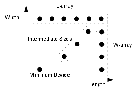
The recommended criteria for selecting devices for extraction is illustrated in the following figure where L-array represents a set of devices with the same width but different lengths and W-array represents a set of devices with the same length but different widths.
Figure 158 Device Size Selection
|

|
A quantity Reff is defined to aid visualization of the scaling rules. For devices on the L and W arrays respectively:
-
 or
or 
For the other devices:
-

|

