|
|
|
05/13/15 |
|
|
Accurate measurement of capacitance and resistance was needed for many
years and many efforts have been put into it. For instance, different
bridge arrangements were proposed, such as Wheatstone bridge (measuring
resistances), Schering’s bridge (measuring capacitances with series
loss), Maxwell bridge (measuring capacitances with parallel loss), Hay
bridge (measuring inductances with series loss) and Wien-Robinson bridge
(measuring frequency). The dissipation factor of a capacitor is the ratio of its resistance to its capacitive reactance. The Schering Bridge is basically a four-arm AC bridge circuit and its measurement idea is based on balancing the loads on its arms. The figure below shows a circuit diagram of the Schering Bridge. In this figure, R1 and R2 are known, while R3 (Series resistance of the test capacitor) is unknown. C1 and C2 are also known, while C3 is the value being measured. To measure R3 and C3, the values of C2 and R2 are fixed, while the values of R1 and C1 are adjusted until the current through the ammeter between points A and B becomes zero. This happens when the voltages at points A and B are equal, in which case the bridge is said to be "balanced". In this state, the followings hold: R3 = C1*R2/C2 and C3 = R1*C2/R2. Note that the balancing of a Schering Bridge is frequency-independent. Because of the inductance of the resistances, we forced to put a capacitance in parallel with the resistances to compensate their inherent inductances. Also, for accurate measurement in high voltage tests, shielding of the circuit components is of crucial importance. |
||
|
Circuit diagram of Schering Bridge. |
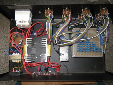
Final product. |
||
This site was last updated 05/13/15