|
|
|
05/13/15 |
|
|
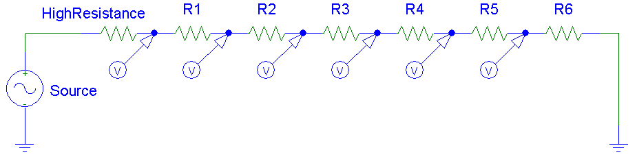
This device can measure the potential difference between two points ranging from 4kV to 24kV. This range can be easily modified by changing the resistors. The structure of this volt meter is simple. There are a number of resistors connected in series and the voltage drop across each resistor can be calculated using kirchhoff's law (voltage divider). The following figure shows the simulated circuit in PSPICE. LEDs were used in this circuit which turn on when their terminal voltage reaches 10 V. For larger values of resistors we used several 330k Ohm resistors in series. There are six LEDs. Each one will turn on if the primary voltage exceeds 4 kV. Therefore, we can only measure the voltage with steps of 4 kV. For a higher resolution, more resistors and LEDs should be added. This instrument is flexible in terms of modifications. Half of the resistors are inside one rod and the other half in the other. Each rod is 1.2 m long and a 3.5 m wire connects them. | |
|
A voltage divider with multiple steps. |
||
|
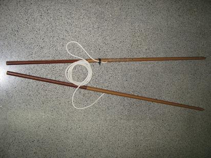
High-voltage phase meter with two rods and connecting wire. |
This site was last updated 05/13/15