![]()
This section describes the CMC TH1000 Mixed-Signal Test Head. The CMC Test Head is a test fixture that supports the testing of both analog and digital ICs. It is designed so that it can easily interface with the timing and pattern pods from the HP VXI Test System. The test head has three fixed power sources (+5 V, +15 V, -15 V) and five programmable power sources that can supply voltage in the range of -20 V to +20 V. In addition to the voltage, the current on each programmable power source can be controlled as well. The voltage and current limits are programmed via a RS-232 interface (standard serial port) that is connected to the HP 700i Workstation. The command set is text based and follows the conventions of the SCPI protocol used by VXIbus modules.
The test head has eight connectors on four sides (side A, B, C, D, 2 connectors on each side). One of three types of signal adapter boards can be connected to each connector. The SAB_D20T can be used to connect the timing pod from the HP E1450A Timing Module. The SAB_D20P can be used to connect a pattern pod from the HP E1451/2A Pattern Modules. Finally, the SAB_Custom signal adapter board has 16 BNC connectors that can connect coaxial cables equipped with BNC connectors to VXIbus modules for testing analog devices.
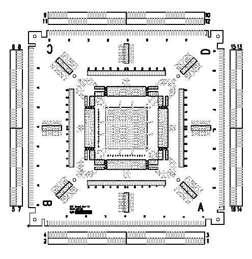
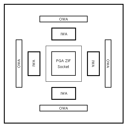
At the top of the test head is the Device Under Test (DUT) board. The overhead view of the DUT board is shown on Figure 2 below. In the middle of the DUT board is a Pin Grid Array (PGA) Zero Insertion Force (ZIF) socket. The ZIF socket can accept chip sizes up to 16 pins by 16 pins. Just outside of the ZIF socket, there is a Inner Wiring Array (IWA) on each side. Each IWA block has 64 pins that map to the pins of the ZIF socket. Surrounding the IWAs are four Outer Wiring Array (OWA) blocks. Each OWA block has 64 pins that connect to the connectors on each side of the test head. In order to make a connection to the DUT from an external source, jumpers need to be connected from the pins of the OWA blocks to the appropriate pins of the IWA blocks. Moreover, there are relays between the OWA and the actual external connectors that connect to the timing and pattern pods. These relays must be turned on before the signals can propagated to the DUT in the ZIF socket. Relays are controlled via the RS-232 interface. Power connections, however, can be connected directly to the appropriate IWA block pins. The power sources are located conveniently to the left of the DUT board. Figure 3 shows the location of the IWA blocks and the OWA blocks with respect to the ZIF socket.

Figure 2: CMC Test Head Device Under Test Board

Figure 3: Location of OWA and IWA blocks.
The following is a summary of the features of the CMC TH1000 Mixed-Signal Test Head:
The process of fixturing a DUT on the DUT board can be a very tedious as all connections from external sources need jumpers from the IWA blocks to the OWA blocks. To make the task of connecting these jumpers easier, CMC has developed a program to graphically show the connections. The VXI Test Head Fixturing Software Version 3.1 (vxi_sunos) allows the user to enter the connections required and outputs a picture of the jumper connections. A step by step description of how to use this tool is available in CMC's digital test tutorial.
Since connecting a DUT on the DUT board is very troublesome, the CMC Test Head has a feature that allows the DUT board to be taken out very easily. Several people can be working with the test head and all that is needed is to replace the DUT board. The jumper connections do not have to be reconnected.
The next section describes the digital design process and how it is related to the physical testing process.