![]()
This section describes the HP VXI Test System. The HP VXI Test System consists of the HP E1401A High-Power Mainframe which accepts VXIbus compliant cards from different vendors. The VXIbus is a standard that combines the features of the HP-IB interface and the VMEBus and is supported by various instrumentation vendors. A wide variety of VXIbus compliant test equipment is available from vendors such as HP and Tektronix. Test equipment modules plug into the mainframe and are connected together via the VXI backplane. In the first slot is the HP E1406A Command Module which is connected to the HP 700i Workstation via a HP-IB (IEEE-488) interface. The workstation can send commands to all modules connected to the backplane via the HP-IB interface. All VXI compliant modules can be programmed via the HP-IB interface with the SCPI (Standard Commands for Programmable Instrumentation) high-level language. The SCPI language consists of simple to understand text based commands.
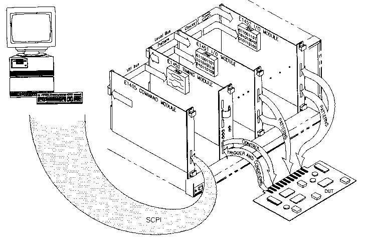
In the UBC VLSI Lab, the HP E1401A High-Power Mainframe is equipped with the HP 75000 Model D20 Functional Test System (D20). The D20 consists of 3 VXI modules: E1450A Timing Module, E1451A Pattern Module and E1452A Pattern Module. In addition, to support the testing of analog ICs, the mainframe is also equipped with a HP E1445A Arbitrary Waveform Generator (AWG) and a HP E1430A Digitizer. The VXI modules that support analog testing will be described in more detail in the section Analog Testing.
The D20 is capable of providing digital signals to a device under test (DUT) as well as measuring the digital responses. The responses can either be recorded or can be compared to expected results that have been programmed into the pattern module's memory. In a comparison test, the test is stopped if a response does not correspond to the expected result. By using this feature, ICs can be determined to be good or bad by a simple pass/fail result from the comparison test.
The timing module provides control outputs to the DUT and generates the timing cycles required to synchronize the test pattern output of the pattern modules. There are eight control outputs that can be used as clocks, data strobes, and other types of control signals. The timing module also has ten condition inputs that can be used to trigger the generation of timing cycles. For example, the pattern module can delay the output of test patterns until a condition becomes true. The timing module has a SCSI-like connector for a timing pod to be connected. The timing pod is an interface between the timing module and the DUT.
As mentioned above, the pattern modules can be used to output stimulus signals or measure response signals. Each pattern module has four 8-bit ports numbered 0-3. Ports are organized into groups that are suitable for the DUT. The largest pin group allowed is 32-bits (4 ports). All four ports in a pattern module are identical and can be used to output stimulus, record responses or compare responses. Two pods are connected to a pattern module's SCSI-like connectors; therefore, each pod consists of two ports. Each port has 64 KB of memory to store expected results in comparison mode.
The following diagram illustrates the relationship between the modules of the D20.

Figure 1: HP 75000 Model D20 Functional Test System
The next section describes the CMC Test Head.