![]()
This subsection describes the steps that need to be carried out in the HP Test Development Software to create a series of SCPI commands that can be loaded into the D20 hardware by the VEE program. The following steps are required:
The first step is to define the pin groups for the control signals, stimulus outputs and response inputs. Figure 9 is the pin group definition dialog box for the 74LS165 example. For the 74LS165 example, 2 clocks (CP1 and CP2) and three pattern I/O pin groups are defined. The response group is defined as a comparison group. Pin groups can be defined with the Configure->Define Pin Groups menu item.
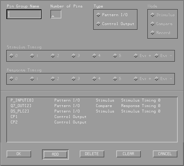
Figure 9: Define Pin Group Dialog Box
After defining the pin groups, the software automatically assigns hardware connections. These settings can be changed with the Configure->Change Hardware Connections menu item. Figure 10 and 11 show the change hardware connections dialog box for the control signals and pattern I/O signals. As shown on Figure 11, the pattern I/O pin groups are connected to module 2 (HP E1452A), ports 0 to 2.
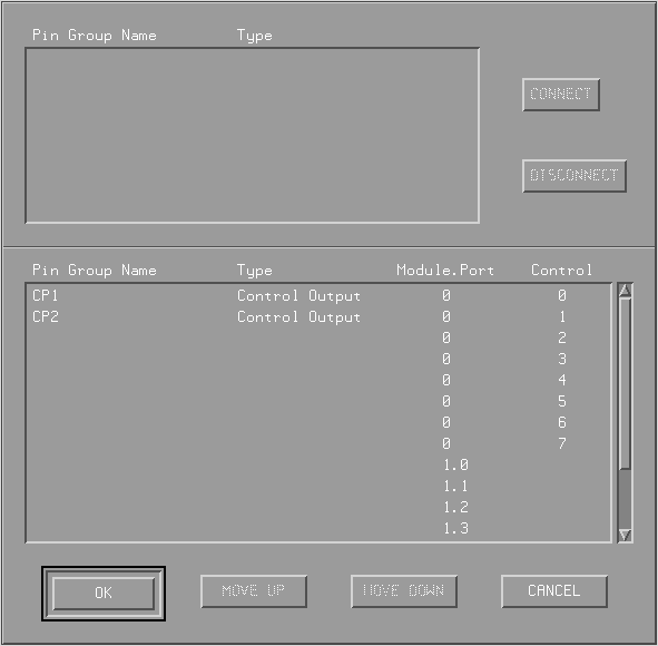
Figure 10: Change Hardware Connections Dialog Box - Control Signals
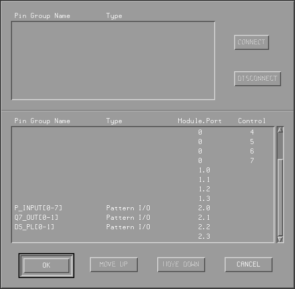
Figure 11: Change Hardware Connections Dialog Box - Pattern I/O
After defining pin groups, then the timing information for each pin group and the control signals need to be entered in the timing window. But before this can be done, the resolution of the grid in the timing window needs to be defined. One box in the timing window is a subcycle. The resolution can be set with the Configure->Set Timing Resolution menu item. Figure 12 shows the set timing resolution dialog box. As mentioned in the Test Development Software section, the minimum timing resolution is 6.25 ns.

Figure 12: Set Timing Resolution Box
The timing information can be entered in the timing window shown on Figure 13. For the 74LS165 example, there is only one timing cycle called LS165_TEST. This timing cycle is 11 subcycles long (0-10). The length of the two stimulus groups use the same timing and the signals are valid in the first subcycle as indicated in the figure. The arrow indicates when the D20 hardware should sample the response. All the settings can be entered by selecting a box on the grid and clicking on the right mouse button. A menu will appear with a list of choices for the selected box.
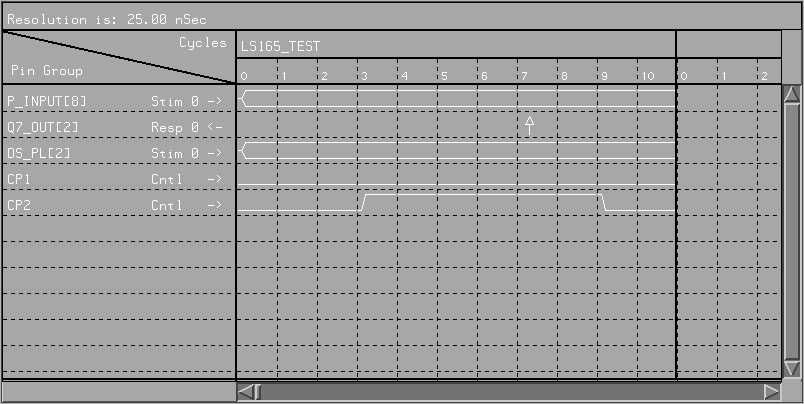
Figure 13: Timing Information Window
After defining the timing information, the PCF file with the test vectors can be imported into the spreadsheet. The menu item Files->Import can be used to do this. A dialog box will appear to prompt the user for a file name. All the test vectors will be translated and stored in the spread sheet window. Figure 14 shows the spreadsheet of the 74LS165 example after the test vectors have been imported.
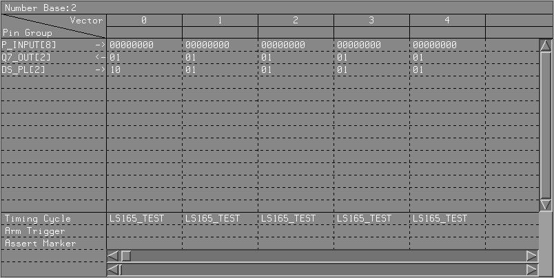
Figure 14: Test Vectors Spreadsheet
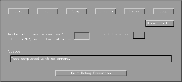
Figure 15: Run Test Dialog Box
To debug connection problems, the direct I/O feature of the software can be used. To use this feature, click on the Direct I/O button in the Run Test dialog box. The Direct I/O dialog box, shown on Figure 16, will appear which allows the user to output signals to the stimulus pin groups manually and read the current values of the response pin groups.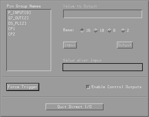
Figure 16: Direct I/O Dialog Box
The final step is to export the test in a text file. The text file (.ASC file) will contain a list of SCPI commands for the D20 hardware that load the test vectors and timing information into the timing and pattern I/O modules. The menu item File->SCPI is used to perform this task.