![]()
This subsection describes the VEE program for the physical testing of digital ICs. The same VEE program can be used for the 74LS181 example in the next section. As mentioned in the VEE Test section, there are four functions in the VEE program:
The following is divided into four subsections. Each subsection describes one of the steps listed above. No VEE programming specifics have been included. The reader should consult the VEE manuals for the usage of the the VEE Test development environment and the VEE objects.In VEE, there are two different views: detail and panel. The detail view is for programming while the panel view is for running the program. After a program has been written, the programmer can lock the program in the panel view so that the user cannot access the details of the program. Figure 17 and 18 show the panel and detail views of the test program respectively. As shown on Figure 17, there are four buttons that correspond to each item in the list above. The user can run the functions by clicking on the buttons.

Figure 17: Panel View of VEE Program
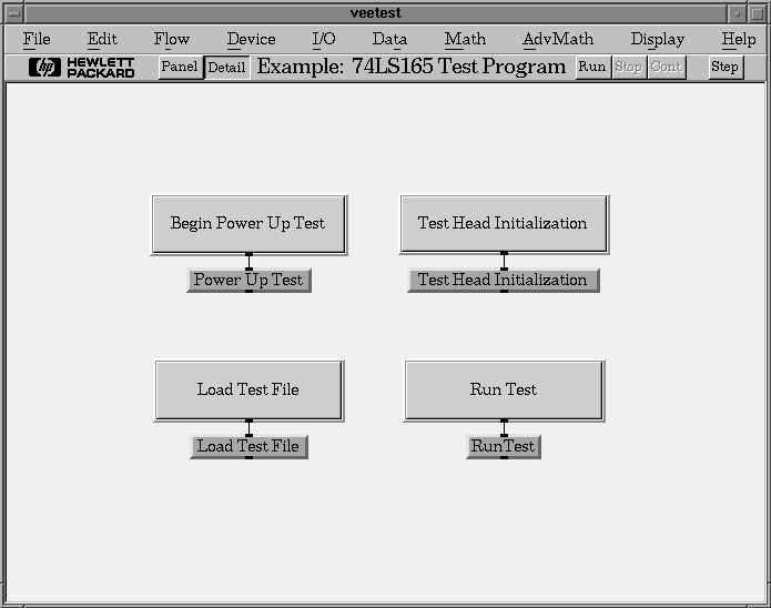
Figure 18: Detail View of VEE Program
The same four buttons are in the detail view. These buttons are made from start objects which allow a user to start a thread. In this case, a thread is a function. Each start button is connected to a function that is iconized. Functions in VEE are made from user objects. To edit a function, select Edit->Edit User Function. A window will appear with the detailed view of the selected function.
Figure 19 is the iconized view of the Power On Self-Test function. This function sends commands to the CMC Test Head to set the voltage and current limits. The voltage is increased gradually to avoid further damage to the chip if there is a short circuit. The function first sends commands to reset the test head. It then prompts the user for the current limit. The power is then gradually increased to 5 volts. During power-up, the voltage and current readings are used to plot two graphs: voltage versus time and current versus time. If the current reaches the limit set by the user, the function is halted with the Exit User Object.
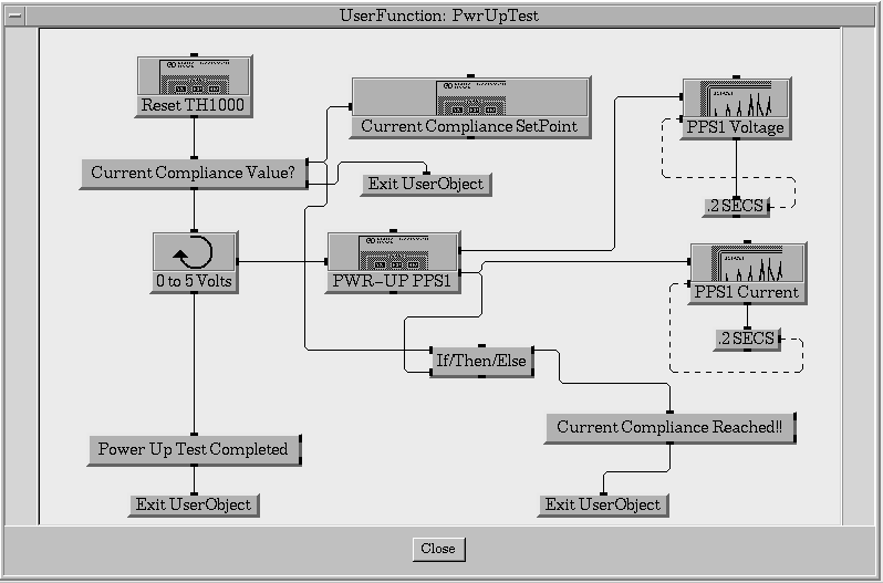
Figure 19: Iconized View of Power On Self-Test
In Figure 19, all VEE objects are iconized. In Figure 20, the objects that send commands to the test head are expanded. The *RST command is used to reset the test head. This is a standard SCPI command that can be used to reset any SCPI compliant device. In the Current Compliance Setpoint box, the first two lines set the current limit for power source 1 and the third line turns on power source 1. Since the voltage has not been set, it is at 0 volts. The PWR-UP PPS1 changes the voltage of power source 1 and retrieves the current voltage and current readings from the test head.

Figure 20: SCPI Commands for Power On Self-Test
Figure 21 shows the voltage and current plots at the end of the Power On Self-Test. The test ended after the voltage has reached five volts. If the current limit is reached, then a "Current Compliance Reached" message box will appear instead of the "Power Up Test Completed" message box.

Figure 21: Running the Power On Self-Test
Figure 22 shows the simple Test Head Initialization function. Like the Power On Self-Test function, It uses a serial object to send SCPI commands to the CMC Test Head. Figure 23 shows the expanded view of the serial object. The :ROUTE:SIG (@0>255) turns on all 256 relays to connect all pod connectors to the outer wiring array (OWA). The *OPC? command waits until the :ROUTE:SIG command has completed before returning a 1. When the test head returns a 1, the if statement executes and outputs a message box indicating that the initialization procedure has completed.
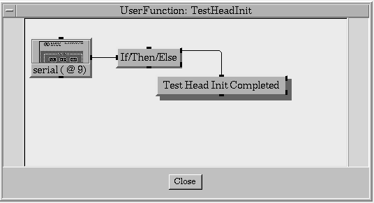
Figure 22: Iconized View of Test Head Initialization
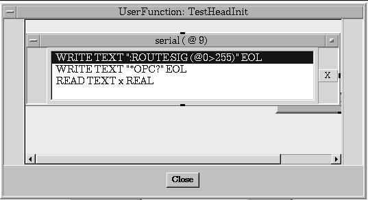
Figure 23: Expanded View of Test Head Initialization
This function can be used to turn on all the relays when debugging the test in the HP Test Development Software. The Run Test function described below also turns on all the relays so this function is not required when using the Run Test function.This function is responsible for loading the SCPI commands from the .ASC file into the D20 hardware. The direct I/O box Reset D20 sends SCPI commands to the D20 to reset the timing and pattern modules, clearing all memory in the process. The Load Test File object is a HP E1450A instrument object and it loads the .ASC file at its input terminal. The file name is selected with the File Name Selection object (Data->Dialog Box->File Name Selection). Since the file name is not hard-coded, other digital tests can use this VEE program. Figure 24 and 25 are the screen shots of the Load Test function.

Figure 24: Iconized View of Load Test
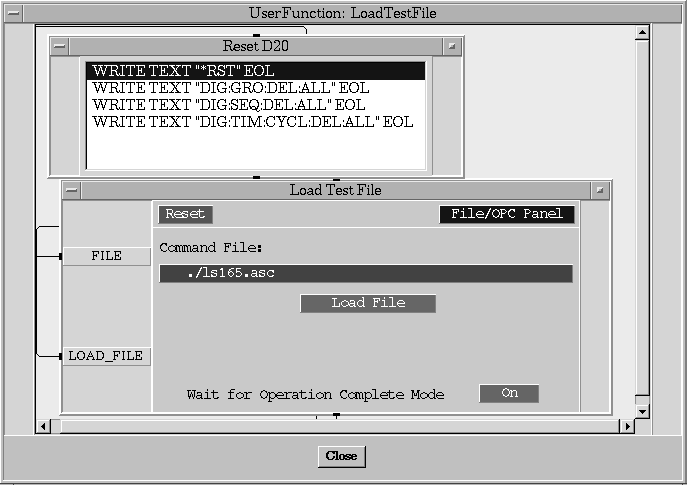
Figure 25: Expanded View of Load Test
The Run Test function is used run the test that has been loaded into the D20 hardware by the Load Test function above. After loading the .ASC file, testing can be performed without reloading the file since all relevant information is stored in the memory of the D20 hardware. During the test, the current drawn by the chip is monitored to ensure that it is less than the current limit. The Run Test function prompts the user for the current compliance value in the same manner as the Power On Self-Test function. Because commands need to be sent to both the D20 hardware and the test head, a multi-device direct I/O object (I/O->Advanced I/O->MultiDevice I/O) is used. The iconized view of the function is shown on Figure 26 and the expanded view of the multi-device I/O object is shown on Figure 27.
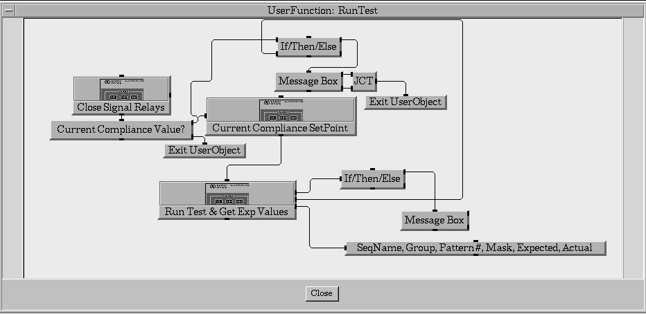
Figure 26: Iconized View of Run Test
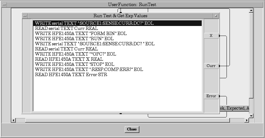
Figure 27: Multi-device Direct I/O Object of Run Test
The SCPI command RUN is used to start the test and the command *OPC? is used to wait until the test has been completed. The FORM BIN command is used to set the format of the data to binary. After the test has completed, the :RESP:COMP:ERR? command is sent to the D20 hardware to get the test result. If no error occurred, then a NULL string is returned.
Figure 28 and Figure 29 show the result of executing the Run Test function. When a test is successful with all actual responses matching all expected responses, the output box at the top is blank. When an error has occurred, then the output box will contain debugging information such as the pin group, the pattern number, the expected response and the actual response. The user can then load the Test Development Software to further examine the cause of the error.

Figure 28: A Test without Errors
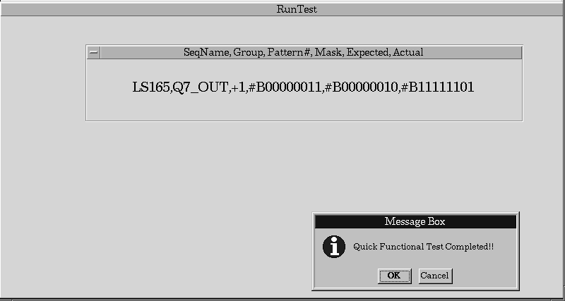
Figure 29: A Test with Errors