Resonant Wireless Power Transfer
Wireless power transfer (WPT) is the transmission of electrical power without wires. The most common method of high-power WPT is through inductive coupling that was invented by Nikola
Tesla more than a century ago. To understand inductive wireless power transfer, one can consider that as a loosly coupled transformer.
Ideal transformers have a coupling factor of 1 and the primary (transmitter) and secondary (receiver) are tightly coupled.
When the distance between primary and secondary increases, the coupling factor drops and the amount of active power, as well as the efficiency of the system sharply drops. This can be seen
as an increase in the transformer's leakage inductance which means most of the transmitter flux does not reach the receiver.
As a result, this type of wireless power transfer is limited to very short range transmission distances (where the coupling is still good) and the efficiency of the system sharply drops
as the separation distance increases.
Resonant Wireless Power Transfer (RWPT) was introduced in 2008 by MIT researchers, and since then, it is gaining a lot
of attention. This technology achieves high efficiency even when the coupling between primary and secondary is not high. This is achieved by adding compensation capacitors to both transmitter and receiver and operating the circuit at a high resonant frequency.
The difference of RWPT with traditional inductive power transfer is that the addition of compensation capacitors causes the imaginary parts of the impedance seen by the source to cancel out and high output power and efficiency can be achieved.
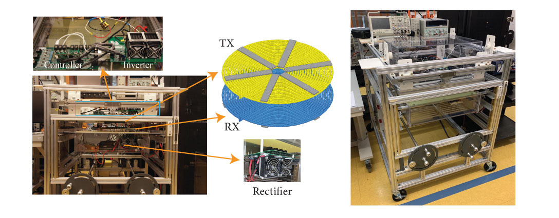
The bellow figure shows the most simple, yet most popular implementation of resonant wireless power transfer which is called series-series compensated WPT.

First, the DC input is converted to a high-frequency AC voltage. This is usually done by using a full-bridge inverter. The inverter output is then applied to the compensation capacitor and transmitter, which is then transmitted
to the receiver side. On the receiver side, the AC voltage is rectified and is delivered to the load. The resonant wireless power transfer can achieve high efficiency over mid-range distances (relative to the coil size). The key to achieving high-efficiency is to operate the circuit at the resonant frequency.
RWPT is widely used in many applications such as mobile phone chargers, kitchen appliances, and wearable electronics and it studied widely for
stationary charging electric vehicles (EVs), and dynamic charging EVs, also called road-powered EVs (RPEVs).
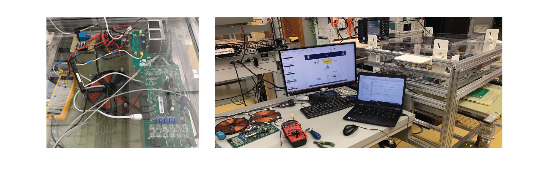
To study different aspects of resonant inductive wireless power transfer, we developed a scallable wireless power transfer platform at
Dr. Ordonez's Power Electronics lab.
The mechanical structure (shown in the below figure) has 4 degrees of freedom to implement different types of misalignment between transmitter and receiver. The purpose of this platform is to mimic different types
of misalignments that happens during EV wireless charging and to study the effects of those misalignments on the performance of the system.
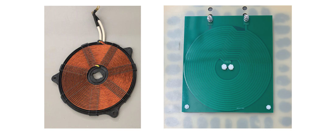
Transmitter and Receiver are two critical parts of a wireless power transfer system and the efficiency of the system highly depends on them.
Coils with high-quality factor (Q) lead to higher efficiency and so optimizing the coils is an important step in designing an efficient wireless power transfer system. Self-compensated coils that use their parasitic capacitance as the compensation capacitor also can be used to reduce the number of circuit elements. Transmitter and Receiver coils can be made using wire or PCB. The following figure shows examples of these coils.
Aside form experimental setup, ANSYS Electronic Suit was widely used in this project to model, simulate, and optimize the system. Ansys MAXWELL was use dto find AC resistance and coupling factor of the
coils under different conditions. It was also used to find quantities of interest such as magnetic flux density, core loss, and current density in the conductors. The following figure shows magnetic flux density
between transmitter and receiver at resonant frequency.

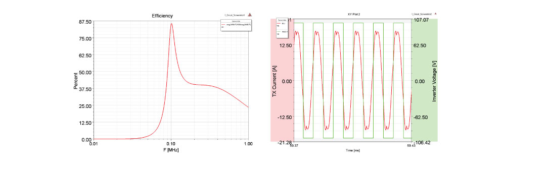
ANSYS Simplorer (now called twin builder) was used along with MAXWELL results to evalluate the behavior and efficiency of the circuit. Co-simulation of MAXWELL and Simplorer allows us to look at
circuit behavior such as switching loss, ZVS operation, required voltage and current rating for circuit components, etc.
Based on the results of this research project, several ideas were developed and corresponding papers are currently under review.
Ali Saket
|
26 Feb, 2020
 Expert, ANSYS, MAXWELL, Q3D, SIMPLORER, ICEPAK, SIWAVE, PEXPRT, PEMAG, EMI EMC Engineer, PCB Designer.jpg)