Planar Transformers with Near Zero Common-Mode Noise
Every commercial power supply should pass EMC tests before going to market and it means that its generated noise should be less than a certain limit.
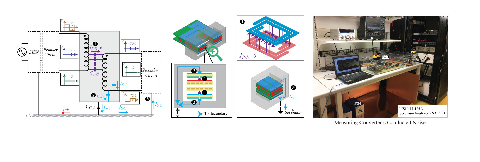
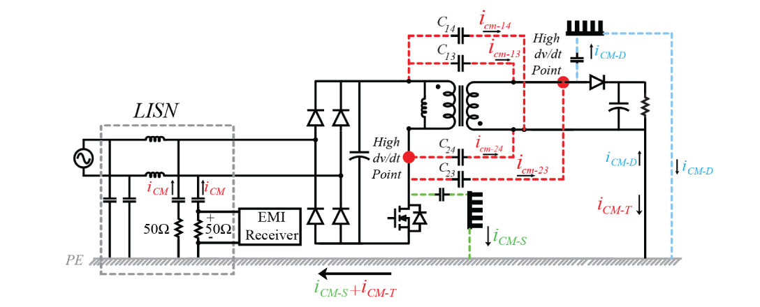
Here, a flyback converter schematic is shown. As you can see, the inter-winding capacitance of the transformer (parasitic capacitance between primary and secondary) provides a capacitive path between primary and secondary and creates displacement currents (known as common-mode (CM) noise) that circulate between primary and secondary through the earth. A large inter-winding capacitance generates high levels of common-mode noise and makes it hard to comply with the standards. Under this condition, large EMI filters are needed to attenuate the noise which reduces
the power density of the converter.
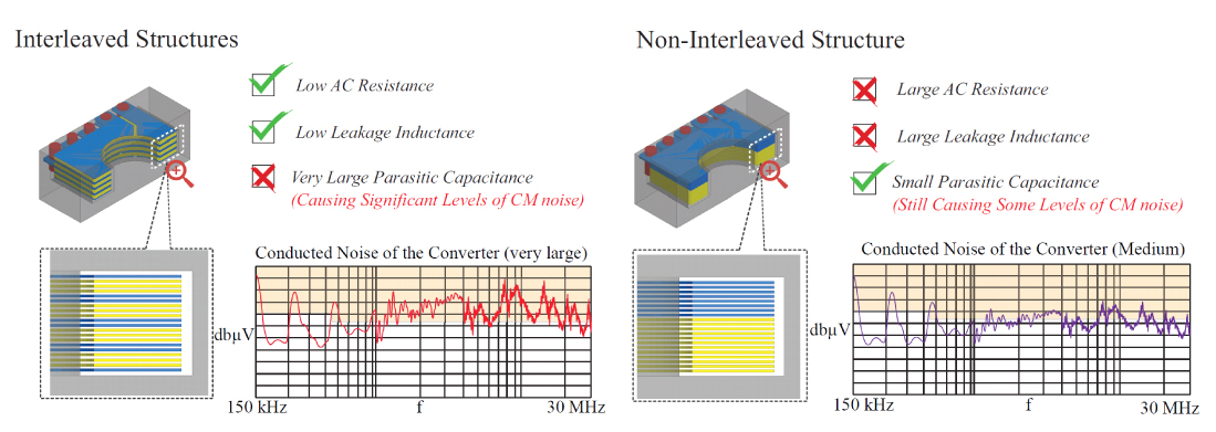
There is a well-known trade-off in transformer design. If we want to minimize AC resistance and leakage inductance, we have to use interleaved structures (where primary
and secondary have multiple overlapping). However, multiple overlapping between primary and secondary means larger inter-winding capacitance and so, large common-mode noise.
On the other hand, if we separate primary and secondary, we have lower CM noise generation, but the price is a larger leakage inductance and AC resistance.
In order to resolve this trade-off, a method called paired layers interleaving is proposed in this project. Using this method, it is possible to design Planar Transformers (PT) that not only have a low AC
resistance and leakage inductance, but also have almost zero CM noise generation.

Paired layers are planar layers that have the same layout and also have similar pulsating voltage on their terminals. It can be shown that overlapping of such layers does not create CM noise. The below figure shows
two twp planar layers that are paired and their equivalent capacitance network model. The dv/dt of point a and c are similar and dv/dt of
points b and d are also similar. Due to the symmetry, the net amount of current in lumped capacitors is equal to zero, and so no CM noise is generated.
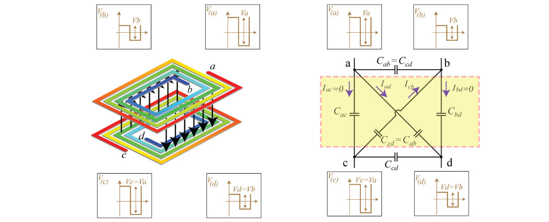
This feature can be used to avoid CM noise generation in planar transformers and at the same time achieve low AC resistance.
In order to validate the method, extensive experimental tests were done and planar transformers with this method were designed for different structures such as LLC resonant Converter,
Flyback, and Forward converters. Experimental results showed that the proposed planar transformers generate a significantly lower amount of CM noise than planar transformers with a similar
parasitic capacitance value and the difference reaches to 20 dB (10 times) and more.
For more information about this project, please refer to the following journal papers:
[1] M. A. Saket, N. Shafiei, M. Ordonez, M. Craciun, C. Botting “Improving Planar
Transformers for Converters with Half-Bridge Inverter: Paired Layers Interleaving,"
IEEE Transaction on Power Electronics (TPEL), Early Access(TPEL).
IEEE Xplore Link,
ResearchGate Link
Ali Saket
|
26 Feb, 2020
 Expert, ANSYS, MAXWELL, Q3D, SIMPLORER, ICEPAK, SIWAVE, PEXPRT, PEMAG, EMI EMC Engineer, PCB Designer.jpg)