High-Frequency Magnetic Design
Magnetic components are major parts of power converters and they significantly affect the performance, efficiency,
and form factor of the converter. Unlike most parts of the power converter that we can buy them off the shelf, usually we have to design
our own magnetics which is customized for our specific application. In power electronics, we deal with different types of magnetics including
filter inductors, AC inductors, forward transformers, flyback transformers, coupled inductors, Common-Mode inductors, and integrated magnetic structures.
As my PhD was about planar magnetics, I had the chance to work on this topic extensively. I have designed and developed different types of magnetic
components ranging from gate-driver transformers with the power of less than one Watt to multi-kW Integrated Magnetic Structures for resonant converters.
My approach in the design is a mixture of analytic design and Finite Elements Analysis. Analytic models are used to get a rough estimation of the core and conduction loss which helps us to achieve a balanced design. However, with the presence of high-frequency eddy losses in the windings,
sometimes the results of these models are fairly inaccurate. On the other hand, the FEA-based design considers these effects but usually takes more time.
ANSYS PExprt is a good software tool to find potential candidates for your design and then tune those designs to achieve desirable performance.
Core loss and Winding loss are two sources of loss in magnetic components. Core loss includes eddy-current loss and hysteresis loss. Winding loss is the conduction loss in the wires of windings.
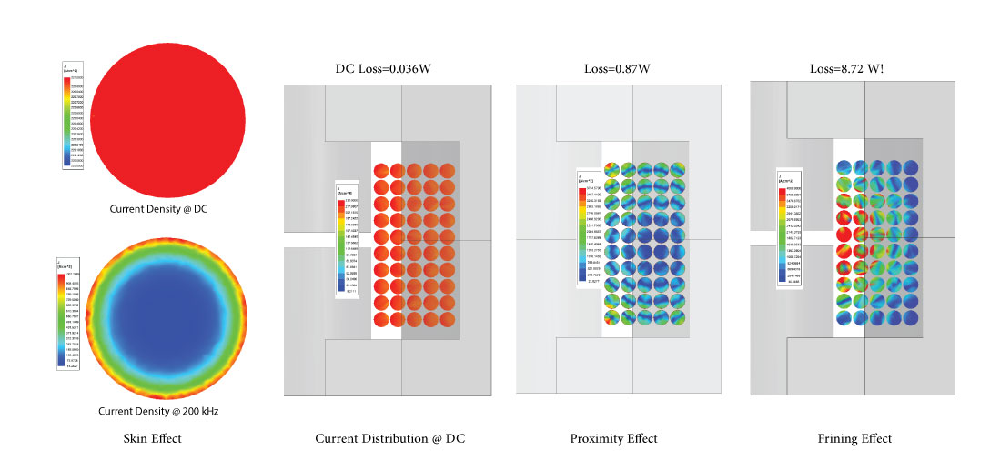
As frequency increases, eddy current effects such as skin effect, proximity effect, and fringing effect significantly increase the winding loss. The following figure shows these effects which are captured using ANSYS MAXWELL. You can see that AC loss significantly differs from the conduction loss at DC. In particular, fringing loss significantly contributes to the AC loss. While skin and proximity effects can be analytically taken into account using Dowel's formula, it is very complicated to include fringing loss in the analytical design. As a result,
the designer might get very surprised to see that a well-designed inductor on the paper gets extremely hot on the bench.
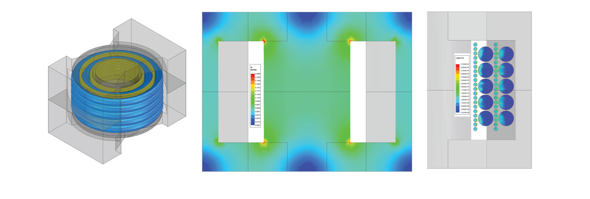
Using FEA, it is possible to accurately find the losses in the design and achieve optimal design with minimum number of prototyping. Quantities of
interest such as magnetic flux density distribution, core loss, current density distribution, winding loss, Parasitic Elements and temperature
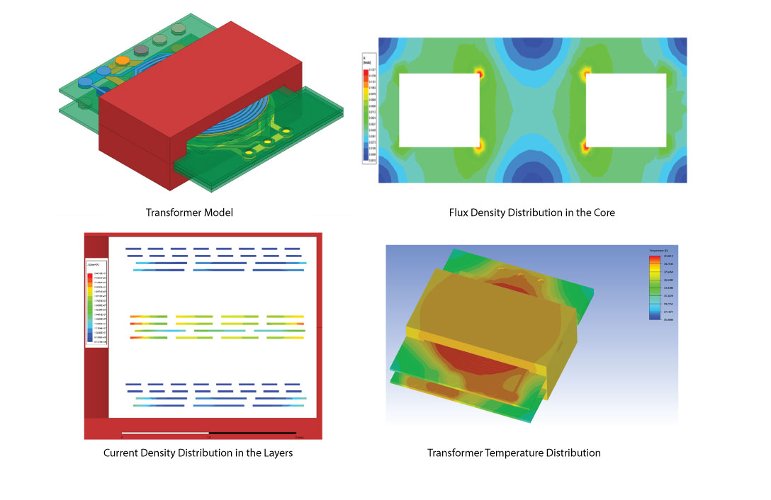
distribution can be found using FEA. The following figure shows a planar transformer designed by me and its FEA using ANSYS MAXWELL and ICEPAK.
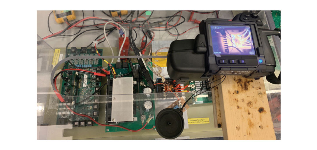
The final design stage is testing for circuit performance and thermal management. The following figure shows a multi-kW LLC resonant converter that I
prototyped at
Dr. Ordonez's Power Electronics lab for testing high-power magnetic components. Thermal camera shows the temperature distribution of the transformer which is in agreement
with the results of ANSYS ICEPAK.
The results of my research on planar magnetics are published in a number of journal
and conference papers which can be found in the
publication page of website
Ali Saket
|
26 Feb, 2020
 Expert, ANSYS, MAXWELL, Q3D, SIMPLORER, ICEPAK, SIWAVE, PEXPRT, PEMAG, EMI EMC Engineer, PCB Designer.jpg)