Troubleshooting

Before troubleshooting or repairing the instrument, make sure the failure is in the instrument rather than any external connections. Also make sure that the instrument was accurately calibrated within the last year (see Calibration Interval). The instrument’s circuits allow troubleshooting and repair with basic test equipment.

Caution

DO NOT swap the motherboard or the front panel board from one instrument to another. These boards contain model number and serial number information that uniquely identifies a specific unit, and boards that are mismatched to the instrument may result in problems with its performance, licensing, serviceability, importability/exportability or warranty.

Troubleshooting Procedure

  1. Remove all remote I/O connections and front panel connections to the instrument. Verify that:
    1. the AC mains power cord is securely connected to the instrument and plugged into a live outlet
    2. the front panel Power On/Standby switch has been pushed
  2. If the standby light below the power switch is not illuminated, re-verify the items above. If all this is correct, check the AC mains power and then the internal line fuse.
  3. If the standby light is on (yellow or green), press the power button. If there is no response, replace the front panel board because the power button on the front panel board is likely broken.
  4. Check the voltages on the power supply. If one or more of these tests fail, disconnect the transformer secondaries from the main board and measure the voltages from the transformer with an AC voltmeter.

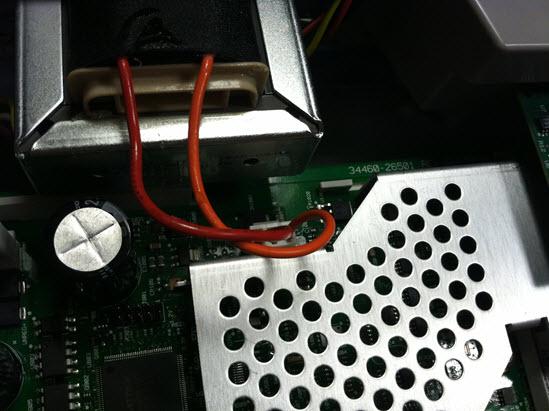
    The voltage between the red and orange wires (below)should measure 7.5 to 11 VAC.


    The voltage between the brown and white wires (below) should measure 11 to 15 VAC.


  5. If the voltages are correct, replace the main board; otherwise replace the transformer.
  6. Turn the instrument on. If the power-on sequence completes and the display appears to function properly, verify that the instrument is in local mode (the Remote annunciator in the upper right corner of the display is not on), and run the full self-test ([Utility] > Test/Admin > Self-Test > Full Test). If the display is illegible, replace the front panel board.

  7. Caution

    Ensure that all connections (front and rear) are removed when self-test is performed. During self-test, errors may be induced by signals present on external wiring, such as long test leads that can act as antennas.
  8. If the self test generates an error, record the error code and message and contact Keysight support if necessary.
  9. If the self test does not generate an error:
    1. If remote I/O on GPIB (optional) is not working, replace the GPIB board.
    2. If the measurements are out of specification, you may wish to calibrate the instrument before deciding to replace the main board.
    3. If the front panel buttons are not working, make sure the unit is in local mode (the Remote annunciator in the upper right corner of the display is not displayed). If that does not solve the problem, replace the front panel board.
    4. If the display is dim, adjust the display intensity.
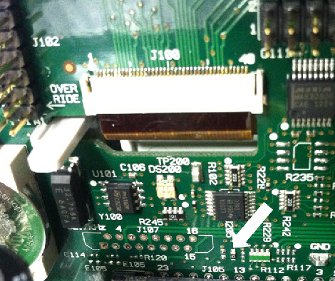
  10. If the instrument does not complete the power-on sequence, check the signal frequency at test point TP200 on the front panel board and verify that it is 29.8 kHz ± 500 Hz. If the frequency is not correct, replace the front panel board.
  11. Also verify that the voltage is 3.3 V ± 5% at resistor R121, referenced to the instrument chassis. If this voltage is incorrect, replace the front panel board.