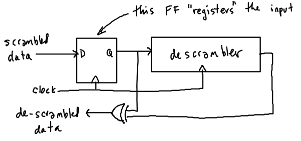
While the diagrams in the V.22 standard as shown in the lecture notes explain the logical operation of the scrambler/de-scrambler, they are not practical logic circuits. In particular, they do not show how a clock signal would be connected.
A problem arises because the rising edge of a clock has to happen earlier than changes in the input in order to meet flip-flop set-up time requirements.
In the V.22 diagrams the input signal is XOR'ed with the output of the flip-flops. In a practical system these two signals will be offset from each other in order to meet the setup time requirements (typically by between a half and a full clock period). This will result in incorrect output from the descrambler.
The simple solution is to "register" the input signal by putting it through a flip-flop that uses the same clock as the rest of the descrambler. The output of this flip-flop is then used as the input to the descrambler. This ensures that transitions of the (registered) input happen at the same time as transitions at the outputs of the flip-flops.

Another practical issue is that the output is a logic function (xor in this case) of two signals. Differences in propagation delays between the inputs to this function will result in glitches in the output. This is undesirable if this signal is going to be extended a long distance such as over a cable. The solution is to register the output in a similar fashion.
Both of these add delays of up to one clock period each which must be taken into account (for example, other signals may need to be delayed by equal amounts).
Version 13 of Quartus II supports vector waveform files directly. So you do not need to run the quartus_sh --qsim command from the command line to start the simulator. Simply open the waveform file from Quartus II. You may want to click on "Add file to current project" in the Open File dialog box so the file name is remembered.