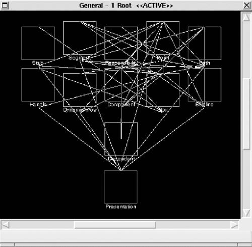
Table of Contents Previous Section Next Section

10.5 Reconstruction

At this point, the view information has been extracted, stored, and refined or augmented to improve its quality. The reconstruction operates on views to reveal broad, coarse-grained insights into the architecture. Reconstruction consists of two primary activities: visualization and interaction and pattern definition and recognition. Each is discussed next.

Visualization and interaction provides a mechanism by which the user may interactively visualize, explore, and manipulate views. In Dali, views are presented to the user as a hierarchically decomposed graph of elements and relations, using the Rigi tool. An example of an architectural view is shown in Figure 10.6.

Figure 10.6. An architectural view represented in Dali

graphics/10fig06.jpg

Pattern definition and recognition provides facilities for architectural reconstruction: the definition and recognition of the code manifestation of architectural patterns. Dali's reconstruction facilities, for example, allow a user to construct more abstract views of a software system from more detailed views by identifying aggregations of elements. Patterns are defined in Dali, using a combination of SQL and perl, which we call code segments. An SQL query is used to identify elements from the Dali repository that will contribute to a new aggregation, and perl expressions are used to transform names and perform other manipulations of the query results. Code segments are retained, and users can selectively apply and re-use them.

Based on the architectural patterns that the architect expects to find in the system, the reconstructor can build various queries. These queries result in new aggregations that show various abstractions or clusterings of the lower-level elements (which may be source artifacts or abstractions). By interpreting these views and actively analyzing them, it is possible to refine the queries and aggregations to produce several hypothesized architectural views that can be interpreted, further refined, or rejected. There are no universal completion criteria for this process; it is complete when the architectural representation is sufficient to support analysis and documentation.

Suppose that our database contains the subset of elements and relations shown in Figure 10.7. In this example variables a and b are defined in function f; that is, they are local to f. We can graphically represent this information as shown in Figure 10.8.

Figure 10.7. Subset of elements and relationships

graphics/10fig07.gif

Figure 10.8. Graphical representation of elements and relationships

graphics/10fig08.gif

An architectural reconstruction is not interested in the local variables because they lend very little insight into the architecture of the system. Therefore, we can aggregate instances of local variables into the functions in which they occur. An example of the SQL and perl code to accomplish this is shown in Figure 10.9.

The first code portion updates the visual representation by adding a "+" after each function name. The function is now aggregated together with the local variables defined inside it. The SQL query selects functions from the elements table, and the perl expression is executed for each line of the query result. The $fields array is automatically populated with the fields resulting from the query; in this case, only one field is selected (tName) from the table, so $fields[0] will store its value for each tuple selected. The expression generates lines of the form:

Figure 10.9 SQL and perl to aggregate local variables to the function in which they are defined
#Local Variable aggregation

SELECT tName
     FROM Elements
     WHERE tType='Function';
print ''$fields[0]+ $fields[0] Function\n'';

SELECT d1.func, d1.local_variable
     FROM defines_var d1;
print ''$fields[0] $fields[1] Function\n'';
<function>+  <function>  Function 

this specifies that the element <function> should be aggregated into <function>+, which will have the type Function.

The second code portion hides the local variables from the visualization. The SQL query identifies the local variables for each function defined by selecting each tuple in the defines_var table. Thus in the perl expression, $fields[0] corresponds to the func field and $fields[1] corresponds to the local_ variable field. So the output is of the form:

<function>+  <variable>  Function 

That is, each local variable for a function is to be added to that function's <function>+ aggregate. The order of execution of these two code segments is not important, as the final results of applying both of these queries is sorted.

The result of applying the code segments is represented graphically in Figure 10.10.

Figure 10.10. Result of applying the code segment in Figure 10.9

graphics/10fig10.gif

The primary mechanism for manipulating the extracted information is inverse mappings. Examples include the following:

  • Identify types

  • Aggregate local variables into functions

  • Aggregate members into classes

  • Compose architecture-level elements

An example of a query that identifies an architectural element is shown in Figure 10.11. This query identifies the Logical_Interaction architectural element, and says that if the class name is Presentation, Bspline, or Color, or if the class is a subclass of Presentation, it belongs in the Logical_Interaction element.

Code segments are written in this way for abstracting from the lower-level information to generate architecture-level views. The reconstructor builds these segments to test hypotheses about the system. If a particular segment does not yield useful results, it can be discarded. The reconstructor iterates through this process until useful architectural views have been obtained.

Figure 10.11 Query to identify the Logical_Interaction element
SELECT tSubclass
    FROM has_subclass
    WHERE tSuperclass='Presentation';
print ''Logical_Interaction $fields[0]'';

SELECT tName
    FROM element
    WHERE tName='Presentation'
    OR tName='BSpline'
    OR tName='Color';
print ''Logical_Interaction $fields[0]'';

GUIDELINES

The following are some practical considerations in applying this step of the method.

  • Be prepared to work with the architect closely and to iterate several times on the architectural abstractions that you create. This is particularly so in cases where the system has no explicit, documented architecture. (See the sidebar Playing "Spot the Architecture.") In such cases, you can create architectural abstractions as hypotheses and test these hypotheses by creating the views and showing them to the architect and other stakeholders. Based on the false negatives and false positives found, the reconstructor may decide to create new abstractions, resulting in new Dali code segments to apply (or perhaps even new extractions that need to be done).

    Figure 10.12 Example of a bad code segment that relies on the explicit listing of elements of interest
    SELECT tName
        FROM element
        WHERE tName='vanish-xforms.cc'
        OR tName='PrimativeOp'
        OR tName='Mapping'
        OR tName='MappingEditor'
    
        OR tName='InputValue'
        OR tName='Point'
        OR tName='VEC'
        OR tName='MAT'
        OR ((tName ~ 'Dbg$' OR tName ~ 'Event$')
           AND tType='Class');
    print ''Dialogue $fields[0]'';
    
  • When developing code segments, try to build ones that are succinct and that do not list every source element. The code segment shown in Figure 10.11 is an example of a good segment; an example of a bad one in this regard, is shown in Figure 10.12. In the latter, the source elements comprising the architectural element of interest are simply listed; this makes the segment difficult to use, understand, and re-use.

  • Code segments can be based on naming conventions, if the naming conventions are used consistently throughout the system. An example is one where all functions, data, and files that belong to the Interface element begin with i_.

  • Code segments can be based on the directory structure where files and functions are located. Element aggregations can be based on these directories.

  • Architecture reconstruction is the effort of redetermining architectural decisions, given only the result of these decisions in the actual artifacts (i.e., the code that implements them). As reconstruction proceeds, information must be added to re-introduce the architectural decisions which introduces bias from the reconstructor and thus reinforces the need for a person knowledgeable in the architecture to be involved.

Playing "Spot the Architecture"

Beginning the process of recovering a "lost" architecture can be daunting. The architecture recovery team begins with a blank slate, from which they need to reconstruct an architecture that is, hopefully, both representative of what is actually there and useful for reasoning about the system, maintaining it, evolving it, and so forth.

But you would not embark on an architectural reconstruction project unless the architectural documentation was either lost completely or at least muddied by time and many revisions by many hands. So, how to begin?

In our first few architectural reconstruction efforts this was not our starting point. We had created Dali and needed some examples to test it on, so we chose a couple of systems that we had architected and built ourselves. We had created these systems with explicit architectures in mind, and so recovering them was not too difficult. Still, the process was not without surprises. We discovered architectural violations even in the relatively small systems we had designed and coded. This encouraged us, for if even our own small and conscientiously architected systems had problems, how bad would large, long-lived commercial systems be? We were emboldened by our successes and eager to tackle such a system.

Our chance came in the form of a large, complex physics simulation. This system had been in development for about six years. It was written in two languages, had no formal architectural documentation, and had not been created with a formal architecture design effort. However, the chief architect felt that there was in fact an architecture in there and that we could recover it with a bit of digging. The system had about 300,000 lines of code, but was probably the most complex system that I had ever seen, and that remains true to this day.

In advance of the architect working with us we were able to get a copy of the code base, from which we extracted many useful low-level relations (such as function_calls_function and function_defines_global_ variable). We loaded the database with these tables.

We then sat down with the architect. He sketched out his view of what the architecture was, and we turned that view into a set of SQL queries, ran these over the database, and visualized the result. It was a mess, with thousands of unclassified elements and thousands of relations going everywhere. Viewing this, the architect thought some more and then proposed a different organization. We again turned this into a set of SQL queries, reorganized the database along these lines and visualized the result. The result was once again a mess.

We continued this for the rest of the day and did more the next day. At the end of that time we finally arrived at an architecture that the architect was reasonably happy with, but it always remained somewhat messy.

What is the moral of this story? First, your initial guesses as to the structure of the architecture may be wrong. You may be required to iterate a number of times before you get something that approaches a rational looking structure. Second, if a product was not created with an architecture in mind, chances are that no amount of post-facto organization will create one for you. You can play "spot the architecture" all you like, but there may in fact be no coherent architecture to spot.

- RK

    Table of Contents Previous Section Next Section