Only Question 1 was marked. It was marked out of 10 although an extra 10% bonus could result in a mark of 11/10. One mark was assigned for each of the following:
The TA will allow the sequence to repeat until he has obtained the group number and then will push the button for 200 ms
if the controller initially goes to Green/Red the TA will push the button for 200 ms to start the first cycle
at this point the TA pushes the button for 200 ms
the TA pushes the button for 20 ms before the light turns to Green/Red
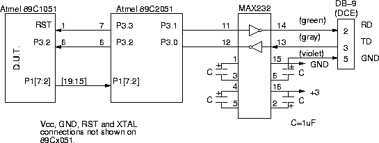
A test program in the 89C2051 receives single-character commands over the serial port and can reset the controller being tested or pull the P3.2 "push-button" input low for either 20 or 200 ms. The 89C2051 also reports the state of the LEDs every time they change. The original purpose was to use an automated testing program to issue commands to the controller and analyze the responses to come up with a mark for each assignment automatically but I ran out of time so the testing had to be done manually.
This is a simple example of how a single-chip microcontroller can be used to implement a "smart" peripheral at low cost.
