The advantages of withdrawing from a course instead of failing.
Notes from lecture on timing analysis, flip-flops arranged in parallel and series (registers) , counters, and counters used as frequency dividers.
Lecture 2 with a few corrections and numbering of the exercises.
"cheat-sheet" for VHDL Synthesis quiz.
Notes from a lecture on counters and timers.
Notes from an introductory lecture on State Machines.
Notes from a couple of Lectures (Feb 21 and 25) explaining Lab 5.
This is a short Learning Hub course that will show you the most important aspects of using an oscilloscope. Go through this material before your first lab.
Note: You must self-register for this course before you can access it. To do this:
Add this to your lab 2 project, create a symbol file and use it in your schematic to debounce the pushbutton switch.
Unfortunately the Quartus version installed in the lab (13.0sp1) has a bug in its VHDL 2008 support so you should use this file instead of the one supplied earlier.
Add this file to your project. It will allow you to instantiate debounce components in your VHDL code.
Version 2: corrected calculation of initial timer value.
Add this file to your Lab 4 project. It can be used to synchronize and debounce your run/stop switch input. Note: the version available before Jan 30 had an error (it used an undefined signal sw0).
Some hints that might help if you're having problems with Lab 4.
VHDL source for the synchronizer/debouncer modified to use a 100Hz clock.
Note: in the previous version of this file the entity was called sync_debounce. In this version the entity has been renamed clk_debounce so that it agrees with the file name and the name used in the lab notes.
This file contains pin assignments corresponding to the port names and pins described in the lab instructions. You can use Assignments > Import Assignments... to import these and save yourself a bit of time if you've used the same signal names and pins as in the lab notes. For the pull-ups to have effect the top-level entity must be named lab5.
Quartus archive for Lab 6 (see lab notes for instructions).
Testbench for lab7.
Video demonstration showing how to use ModelSim to complete lab 7.
Testbench for lab 8.
These are the instructions you will need to follow to complete the lab exam. Please read them before the exam. You should configure and test your breadboard before the exam. It would also be a really good idea to try the two practice lab exams to make sure you know where everything is.
Download and open this file with Quartus to extract the labexam project. Add code to the labexam.vhd file where indicated, compile the project, and program your CPLD.
Program your CPLD with this file to check that you've configured the switches and LEDs on your breadboard correctly. See the Lab Exam Instructions handout for details.
These are practice lab exams you can attempt. They will help to familiarize you with the exam format. When you are done you can upload your VHDL files to the Practice Lab Exam VHDL Folder.
[The VHDL file for the real lab exam should be uploaded to the Lab Exam VHDL folder.]
(You can ignore the warning about the 'r' input not being read -- it is not used by this state machine.)
Annotated lecture slides from Chapter 12 of the textbook. This is the material up to March 7 and covers Memories.
Includes corrections to Question 2 (change y <= y+1... to y_next <= y+1...) and Question 3 (labeled multiplexer inputs).
These may or may not be the datasheets for the components we will be using.
Schematic for the CPLD board used in the lab.
Power must be supplied through the coaxial power connector and by turning on switch J6.
The "USB Blaster" JTAG programming cable does not supply power to the board. It may appear to, but the board is being powered by logic signals from the programmer and may not operate reliably.
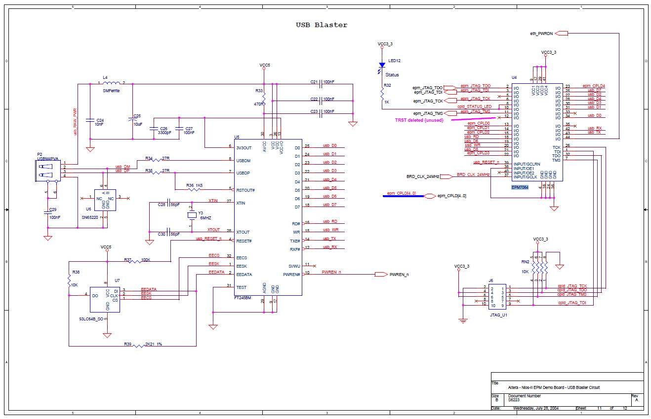
Altera USB-JTAG interface.